Switch disconnectors
A load-break switch , short- load isolator is a switch composed of a combination of a circuit breaker and a disconnector is. Switch disconnectors meet both the requirements of a load switch and the requirements of a disconnector.
construction

The switch-disconnector is similar in structure to an ordinary load switch. The usual design of the switch disconnector is the push load disconnector. So that the switching contacts can also switch loads, arc extinguishing devices are attached to the supports of the switching contacts . The arc is quenched using hard gas . For higher switching capacities, switch disconnectors are also built as vacuum switch disconnectors . With these switches, a metal vapor arc is created instead of the normal arc, which is easier to extinguish due to the existing vacuum. In addition, the switch-disconnector has a visible isolating distance. With newer switches, the isolating distance is visible if the switch has a display device which is directly mechanically non-positively connected to the switch contacts and thus allows an unequivocal switching state to be recognized. The isolating distance is designed in such a way that it has an insulating capacity that meets the required conditions. This means that switching fault protection can be omitted. Since the isolating distance is already integrated in the switch, the separate isolating switch can also be omitted.
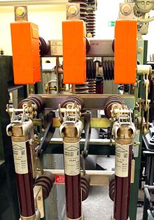
The switches are switched by means of a spring-loaded drive. Remote shutdown using a shunt release is possible via a mechanical release device. In addition to the usual two-position switch-disconnectors, there are also special three-position switch-disconnectors. After the current path has been interrupted, these switches connect the dead contact to earth . This function is used for the safety of the maintenance personnel. Switch disconnectors are suitable for switching off large currents, but their switching capacity is smaller than that of circuit breakers. Switch disconnectors are built for switching capacities from 40 to 63 kA . Switch disconnectors cannot normally switch off short-circuit currents. If short-circuit currents are also to be switched off, the switches are combined with high-performance fuses, as shown in the adjacent figure.
Such switch-disconnectors with an integrated fuse are called fuse switch-disconnectors and are three -pole with three - phase alternating current . The three fuses are often mounted on the same frame as the switch, as shown in the adjacent figure. In the upper area of the fuses there is a firing pin which is pushed outwards by a small propellant charge in the fuse when triggered. As soon as only one of the three fuses responds and the firing pin is pushed out, the system is switched off on all poles by a mechanical linkage and the release of the spring-loaded drive.
commitment
Switch disconnectors are mainly used as main and transfer switches in small medium-voltage distribution systems. Since no disconnectors are required when using switch disconnectors, they are particularly economical in smaller switchgear systems. Switch disconnectors are used to switch unloaded and loaded transformers , cables and overhead lines and reactive current compensation capacitors. Switch disconnectors are also used instead of disconnectors to increase safety in switchgear. In combination with built-on high-performance fuses, they can be used in networks with higher short-circuit power. In low-voltage electrical load break switches for interrupting main circuits in the main distribution used.
Individual evidence
- ↑ Valentin Crastan : Electrical energy supply. Volume 1: Network elements, modeling, stationary network behavior, dimensioning, switching and protection technology. 2nd, edited edition. Springer, Berlin et al. 2007, ISBN 978-3-540-69439-7 .
- ^ Theodor Schmelcher: Handbook of low voltage. Project planning information for switchgear, switchgear and distribution boards. Siemens Aktiengesellschaft (Publishing Department ), Berlin / Munich 1982, ISBN 3-8009-1358-5 .
- ↑ a b Klaus Heuck, Klaus-Dieter Dettmann, Detlef Schulz: Electrical energy supply. Generation, transmission and distribution of electrical energy. For study and practice. 7th, completely revised and expanded edition. Friedrich Vieweg & Sohn, Wiesbaden 2007, ISBN 978-3-8348-0217-0 .
- ↑ a b c d e Réne Flosdorff, Günther Hilgarth: Electrical energy distribution (= guidelines for electrical engineering. Vol. 9). 4th, revised and expanded edition. BG Teubner, Stuttgart 1982, ISBN 3-519-36411-5 .
- ↑ a b c d e Adolf Senner (Ed.): Electrical engineering. 4th edition. Verlag Europa-Lehrmittel Willing, Wuppertal-Barmen 1964.
- ↑ a b c Adolf J. Schwab: Electrical energy systems. Generation, transport, transmission and distribution of electrical energy. 3rd, revised and expanded edition. Springer, Berlin et al. 2012, ISBN 978-3-642-21957-3 .
- ↑ a b c d Klaus Tkotz, Peter Bastian, Horst Bumiller and others: Electrical engineering. 27th revised and expanded edition. Verlag Europa-Lehrmittel Nourney Vollmer GmbH & Co. KG, Haan-Gruiten 2009, ISBN 978-3-8085-3188-4 .
- ^ Paul Waldner: Fundamentals of electrotechnical and electronic building equipment. Werner, Düsseldorf 1998, ISBN 3-8041-3983-3 .
- ↑ Wolfgang Esser: Safe interruption of the main circuits, with switch disconnectors N or with molded case switches NS . Eaton Industries GmbH, Bonn Online (accessed July 30, 2012; PDF; 494 kB).
