Linearizer
As linearizer are electronic circuits , the nonlinear behavior of amplifiers is improved at maximum with the aid referred to.
The implementation takes place, for example, by circuit groups with the inverse behavior of the amplifier. These counteract the non-linearities and minimize the distortions. This increases the linearly controllable power range up to the nominal power of the amplifier. This linearity is particularly important when processing modulated signals . Linearized amplifiers have a significantly higher degree of efficiency with improved signal quality. There are several ways to linearize the amplifier. These include, for example, pre- / post-distortion and feedback circuit concepts. The most common implementation is with predistortion.
How predistorting linearizers work
In real amplifiers, non-linearities occur due to decreasing amplification and phase changes when the output is close to the nominal power. This behavior is commonly known as compression. The predistorting linearizer is designed to compensate for these changes. This is called expansion, analogous to compression.
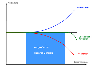
In Figure 1 the gain is represented as a function of the input power. At a certain input power, the amplifier begins to compress (red curve). If a pre-distorting linearizer is connected in front of the amplifier (blue curve), the compression effect is compensated up to a certain power level (green curve). The power level at which the gain of the overall system decreases is thus shifted to higher powers and the linear range is increased. By using the linearizer, the linear output power of the amplifier can be increased significantly (up to four times) in practice.
The increased linear power range is also illustrated in Figure 2 (area highlighted in light blue). The graphic here shows the ratio of input and output power of an amplifier with and without an upstream linearizer. The dashed curve shows the output power of the amplifier as a function of the input power on a logarithmic scale. In this illustration, the compression is shown by the kinking from the ideal 45 ° line. The amplifier with the upstream linearizer (solid line) then deviates from the ideal straight line significantly later. The additional linear range of the output power obtained by the predistorter is highlighted in light blue in the graphic.
Advantages of pre-distorting linearizers
Predistorting linearizers work in the small signal range and only slightly increase the DC power consumption of the overall system. From this u. a. derive further advantages:
- Small dimensions, light weight
- Inexpensive compared to more powerful amplifiers with the same linearity
- Environmentally friendly as the system becomes more efficient
- Can be integrated later
- Adaptation to various amplifier types possible
- Reliable
Typical properties of a pre-distorting linearizer
- Dimensions: depending on the construction technique in the range of a few cm
- Weight: min. 20 g to approx. 200 g depending on the expansion level
- Frequency ranges: 1 to 50 GHz with different bandwidths
- Expansion values:
- Gain: up to 10 dB, depending on amplifier data
- Phase: up to 60 °
application areas
Linearizers are preferably used for power amplifiers with tubes ( traveling wave tubes , klystron , magnetron ) or semiconductors ( GaN , GaAs , Si ). These systems are used in high-speed data transmission systems such as e.g. B. satellite communications , Internet and HD / 3D television are used. A high signal quality is required here. Optimizing the amplifier properties enables ideal power utilization and leads to energy savings of more than 50 percent.
Web links
http://www.astyx.net/satellitenkommunikation/linearisierer.html

