
Magnetron
A magnetron is a vacuum transit time tube for generating electromagnetic waves in the microwave range (approx. 0.3 to 95 GHz ) with an efficiency of up to 80%.
Magnetrons are very efficient, inexpensive generators for high frequency . Power and frequency are largely determined by the mechanical structure and are usually not changeable.
A distinction is made between continuously operating ( continuous wave ) magnetrons and pulse magnetrons. A few kW can be achieved in continuous wave operation and more than 10 MW in pulse operation. Magnetrons are among the electron tubes .

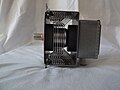
Above: RF output
Right: connections f. Heating / operating voltage.

construction
The magnetron consists of a cylindrical hot cathode (oxide or storage cathode ) in the center of the vacuum tube. The coiled heating wire often forms a directly heated cathode. This is enclosed by a massive, cylindrical anode block made of copper. In the anode block, for example, there are slots (so-called slot magnetrons) that are arranged in a radial pattern and run parallel to the heating wire. The depth of the slots corresponds to about a quarter of the wavelength; it determines the frequency. Depending on the interpretation, there are cavity resonators , conduction circles or waveguides that are open to the inside to the so-called interaction space and short-circuited outside.
In the picture on the right, there are bars that form a segmented anode towards the inside towards the cathode and are connected to a copper cylinder on the back (segment resonator, circular type). The construction can be understood as a circle of pot circles . The segments are alternately coupled to one another by the two rings. This ensures that they oscillate out of phase with one another - the oscillation of other modes (and thus an undesired frequency) is avoided.
Cooling fins on the outside of the anode block enable cooling by free convection , a fan or water cooling.
Other embodiments of magnetron anodes are hole resonator and multi-frequency resonator ( rising sun type).
The magnetron requires an axial magnetic field, which is usually generated with permanent magnets .
One of the cavity resonators is connected to a coupling loop or via a slot to a waveguide and is used to draw power.
Magnetron of a microwave oven from the side: black on the side of the cooling fins: the magnets.

Magnetron of a microwave oven in longitudinal section (magnets and cooling fins removed).

Magnetron of a microwave oven disassembled, exit side on the right

Pulse magnetron MI-189W (7.5 kg, approx. 8 GHz, 60 kW / 0.5 µs, Soviet Union approx. Around 1970)
.jpg)


Mode of action
Electron orbits

In the interaction space between cathode and anode, electric and magnetic fields act simultaneously. The magnetic field lines run parallel to the cathode axis and penetrate the interaction space. If there is voltage between anode and cathode, the electrons released by a hot cathode are accelerated towards the anode due to the electric field . However, the electric field forms a right angle with the magnetic field , so the electrons are deflected spirally from their radial path due to the Lorentz force . As a result, they move in the interaction space around the cathode. Only when the anode voltage is very high does the current flow - the electric field expands the curvature of the path so that the electron paths brush against the anode (green path in the figure).
Resonant anode shape
The slots or chambers of the anode form a ring-shaped closed delay line made up of cavity resonators : Electromagnetic oscillations in one cavity resonator spread through the interaction space and the slots into the other cavity resonators. A ring-shaped, closed multi-pole electromagnetic resonant circuit is created. In it occur alternating voltages between the ends of the anode segments and alternating currents on the inner surfaces of the slit walls. The high-frequency field in this ring resonator interacts with the electrons. The resulting fields influence the path and speed of the electrons. The result is that electrons are slowed down or accelerated and areas of higher and lower electron density are formed during their rotation. These electron clouds in turn amplify the high-frequency oscillations of the ring resonator - self-excitation occurs. If the kinetic energy of an electron becomes too small, it enters the anode block. An excess of free electrons is constantly being supplied from the cathode.
Electrical connection

Magnetrons have an electrically heated glow cathode to release electrons through glow emission . This is often directly heated or a heating connection is connected to the cathode. Since the anode block, magnet, waveguide flange or antenna pin have ground potential, the heating voltage supply of the magnetron (several kilovolts) must be isolated from ground. The operating voltage, which is negative compared to the anode and thus ground, is applied to the cathode .
The illustration opposite shows the typical circuit of a magnetron in a microwave oven: The 2000 V high-voltage winding is earthed on one side and charges the capacitor to around 2800 V via the semiconductor diode when its earth-side end forms the negative pole, while on the magnetron itself only the flow voltage the diode lies. If, on the other hand, the voltage in the high-voltage winding is reversed in the next half-wave, the voltage of the high-voltage winding and that of the charged capacitor connected in series add up to the anode voltage of around 5600 V. Current flows briefly through the magnetron. The combination of capacitor and diode is a voltage doubler . The magnetron only works during a half-wave in the rhythm of the mains frequency.
In the picture of the pulse magnetron MI-189 (МИ-189А to МИ-189Д) it is the red-brown plastic body that isolates the heating voltage and cathode connections from the metal body of the magnetron or the anode. The МИ-189 has an anode voltage of around 13 kV, so the sleeve is correspondingly long.
As soon as the magnetron is put into operation, a small part of the electrons fall back onto the cathode and thermal energy is released. Therefore, especially in the case of continuously operating magnetrons, the heating voltage for the cathode must be reduced during operation in order to avoid excess temperature. A maximum value of the standing wave ratio (VSWR) is also specified in the technical data of magnetrons . A mismatch also leads to overload.
Applications

The main areas of application for continuous wave magnetrons are industrial heating and drying ( HF heating), plasma generation and microwave ovens .
In sulfur lamps and some ion sources , a magnetron is used to generate plasma.
Pulse magnetrons are still often used today in pulse radar devices to generate the transmission pulses.
For sputtering (Engl. For spraying) among other techniques also magnetrons are used.
Very high power impulse magnetrons are used in EMP weapons: Here, directed RF energy is used to attempt to destroy enemy electronics.
history
.jpg)
Before 1912, the physicist Heinrich Greinacher developed a tube to measure the ratio of the charge on the electron to its mass and set up the basic mathematical equations. However, the tube did not work due to insufficient vacuum inside and insufficient electron emission.

The physicist Albert W. Hull from the USA used Greinacher's publication, expanded the theory of the trajectories of electrons in a magnetic field and developed a magnetically controlled amplifier tube, which he named the magnetron. Hull developed the first such magnetron at General Electric (GEC) in 1921, which consisted of several coaxial , cylindrical anode walls ( split anode magnetron ) and a cathode. The arrangement is penetrated by a longitudinal magnetic field from an external coil. The coil current controls the flow of electrons via the magnetic field. The goal was to build magnetically controlled relays or amplifiers. They should compete with the control electrodes made by Western Electric Co. It was discovered that these magnetrons also generated high frequencies.
An independent development took place in 1921 by Erich Habann in Jena and August Žáček in Prague . Habann developed a magnetron with a split anode cylinder that generated frequencies of 100 MHz. The main difference to the Hull magnetron was that Habann (as in today's magnetrons) used a constant magnetic field . Habann was able to precisely calculate in advance the conditions for eliminating the damping (creating a negative differential internal resistance). Žáček was able to achieve frequencies of 1 GHz with a massive cylinder anode. Kinjirō Okabe (1896–1984) at Tōhoku University in Sendai ( Japan ) achieved the breakthrough for magnetrons in the centimeter wave range in 1929 with frequencies of 5.35 GHz through slots in the anode .

On November 27, 1935, Hans Erich Hollmann registered his patent for the multi-chamber magnetron, which was granted on July 12, 1938.
In the spring of 1939, S. Nakajima et al. at JCR Japan the world's first cavity magnetron with a cavity resonator. The magnetron called M-3 was water-cooled and had an output of 500 watts at a wavelength of 10 cm.
In 1940, one year after the Japanese, the British physicists John Turton Randall and Henry Albert Howard Boot developed an improved version of Hollmann's multi-chamber magnetron by using a liquid cooling system and increasing the number of resonance chambers from four to six. This enabled them to multiply the output power a hundred times. Two years later, this enabled the development of very powerful magnetron transmitters for radar devices with a very short wavelength and thus a high resolution .
literature
- Heinrich Greinacher : About an arrangement for determining e / m. In: Negotiations of the German Physical Society. Vol. 14, 1912, ISSN 0420-0195 , pp. 856-864.
- Albert W. Hull : The Measurement of Magnetic Fields of Medium Strength by Means of a Magnetron. In: Physical Review . Vol. 22, No. 3, 1923, ISSN 0031-899X , pp. 279-292, doi : 10.1103 / PhysRev.22.279 .
- Erich Habann : A new generator tube. In: Journal of High Frequency Technology. Yearbook of Wireless Telegraphy and Telephony. Vol 24, 1924. ZDB -ID 1011026-4 , pp 115-120, 135-141, (also: Jena University, Dissertation, 1924).
- August Žáček : Nová metoda k vytvoření netlumených oscilací (Předběžná zpráva). In: Časopis pro pěstování matematiky a fysiky. Vol. 53, No. 4, 1924, ZDB -ID 201513-4 , pp. 378-380.
- Hans E. Hollmann : Physics and technology of the ultra-short waves. Volume 1: Generation of ultra-short-wave vibrations. Springer, Berlin 1936, Chapter 4.
Web links
- Operation of a magnetron (English)
- How a magnetron works (German, English, French, Turkish)
Individual evidence
- ^ The Engineering Handbook, Second Edition . In: Electrical Engineering Handbook . June 29, 2004, ISSN 1097-9409 , p. 1046 , doi : 10.1201 / 9781420039870 .
- ↑ Patent US2123728 : Magnetron. Registered on November 27, 1935 , applicant: Telefunken GmbH, inventor: Hans Erich Hollmann.
- ^ S. Nakajima: The History of Japanese Radar Development to 1945 . In: IEE - London, Peter Pelegrinus Ltd., London (ed.): Proc. of IEE 85 Seminar on the History of Radar IEE 85 . Peter Pelegrinus Ltd., London 1988, p. Chapter 18, pp. 243-258 .