
radar
Radar [ ʁadaːʶ ] is the abbreviation for ra dio d etection a nd r was concerned (translated free "radio-based tracking and distance measurement") or ra dio d irection a nd r was concerned (translated free "radio-based direction and distance measurement"), in the meantime r adio a ircraft d etection a nd r was concerned (translated free "radio-based aircraft tracking and -abstandsmessung") and is the name for various detection and location method and apparatus on the basis of electromagnetic waves in the radio frequency range ( radio waves ). The term radar has the original German name in the past Funkmeß replaced.

General

A radar device is a device that emits a so-called primary signal as a bundled electromagnetic wave that receives the echoes reflected from objects as a secondary signal and evaluates them according to various criteria. In this way information about the objects can be obtained. Mostly it is a question of a location (determination of distance and angle). Depending on the application, there are different radar principles such as weather radar , harmonic radar and above-horizon radar .
From the received waves reflected by the object can u. a. the following information can be obtained:
- the angle or direction to the object
- the distance to the object (from the time difference between sending and receiving, see the speed of light )
- the relative movement between transmitter and object - it can be calculated by the Doppler effect from the shift in the frequency of the reflected signal
- the stringing together of individual measurements provides the distance and the absolute speed of the object
- If the radar has a good resolution, the contours of the object can be recognized (e.g. the type of aircraft) or images can even be obtained (earth and planet exploration).
The electromagnetic wave propagating by radar is sometimes also referred to as radar radiation . One also speaks of a radar beam , in particular when the radiation from the radar device is largely bundled in one direction due to the antenna design . The radiation pattern of the antenna then has a so-called lobe shape .
Since the wavelength of the radar according to the application and prior art in the field of radio waves in the short to the microwave region is located, the name was originally Funkmeßtechnik (short Funkmeß ) was used. It was replaced by the term radar in the Federal Republic of Germany after the Second World War . In the GDR , radio measurement technology was still used in technical language .
history
discovery


In 1886 Heinrich Hertz found experimental evidence of electromagnetic waves that radio waves are reflected on metallic objects.
The German high-frequency technician Christian Hülsmeyer carried out the first attempts at location with the help of radio waves in 1904. He found that electrical waves reflected from metal surfaces can be used to detect distant metallic objects. His telemobiloscope for the detection of ships is considered to be the forerunner of today's radar systems and was applied for a patent on April 30, 1904. The benefit of radar technology was initially not recognized and so the invention was temporarily forgotten.
Development of modern radar systems in the Second World War
The Scottish physicist Sir Robert Alexander Watson-Watt , FRS FRAeS (1892–1973) is considered to be one of the inventors of the radar. Watson-Watt was initially an assistant at the Department of Natural Philosophy at University College in Dundee, then part of St Andrews University . In 1927 he became director of the Radio Research Station at Ditton Park near Slough . From 1936 he was director in the Air Ministry . He did research on the reflection of radio waves in meteorology. In 1919 he patented a method for locating objects by means of radio waves (radar) which, after further developments (development of the visual or short-term direction finder; Watson-Watt direction finder), could be used for the first time in 1935 for the radar localization of aircraft in the meter wave range. On February 26, 1935, he attempted to use radar to detect the Handley Page HP50 bomber , which was approaching Daventry as a test . Watson-Watt was instrumental in the development of British radar systems during World War II.
The breakthrough in radar technology followed shortly before and during the Second World War . In the course of the military armament during this period, radar devices and systems were developed intensively in several countries independently of one another from the mid-1930s, especially by the Germans and the British. When the war began in 1939, there were also radar systems in the USA, the Soviet Union, France, Japan, Italy and the Netherlands.
On the German side, Rudolf Kühnhold, as the scientific director of the intelligence test department of the Reichsmarine, played a large part in the development. A radar device he developed, called DeTe device ( decimeter telegraphy ) for camouflage , was first tested in 1934 in the port of Kiel to detect ships. The British carried out a first field test on February 26, 1935, in which aircraft could be tracked up to a distance of 13 km. In September 1935, GEMA from Berlin was the first to present a fully functional radio measuring device .
In addition to GEMA, which developed systems such as Freya , Mammut , Wassermann and Seetakt , Telefunken was also significantly involved in German radar technology with the Würzburg and Würzburg-Riese systems . On December 18, 1939, the Luftwaffe flew its first radar-guided interception mission against 22 British bombers that were attacking Wilhelmshaven . In the aerial battle over the German Bight , she managed to shoot down twelve of them and seriously damage three. The German defense system against bomber squadrons, the Kammhuber Line , ran over a length of more than 1000 km from Denmark to northern France.
Starting in 1936, the British also set up Chain Home , a chain of radar stations on the east coast that worked on a different wavelength than that of the Germans and was initially not recognized by them. As early as 1939, the system was supplemented with a friend-foe recognition device in the aircraft. A milestone in radar development was the invention of the magnetron at the University of Birmingham at the beginning of 1940 , which was to become the core device of all later radar applications.
At the end of January 1943, during an attack on Hamburg , the British first used a mobile radar system in aircraft that was used for navigation ( H2S ). Both sides developed so-called chaff , simple strips of metal foil to disrupt the opposing radar systems. However, improved systems that could filter out these interferers were quickly developed.
Research after World War II
In Germany, research in the field of radar came to a complete standstill after the war. The Allies banned this until 1950. The research made considerable progress in the period that followed, particularly in the USA, where numerous new theoretical approaches and innovative components such as semiconductors were developed. The Synthetic Aperture Radar from 1951 is an example .
On-board radars are also standard equipment on board civil aircraft and ships. One of the first and to this day most important civil applications is the monitoring of air traffic using Air Traffic Control (ATC).
The first distance warning radar systems for the automotive sector were developed as early as the late 1970s. Radar technology has been used in space travel since the mid-1990s, primarily to measure the earth and other planets. Weather radars are also used to collect weather data .
Areas of application


Radars are designed for a variety of uses:
-
Panoramic radar ; Monitoring of shipping and air traffic (including early warning stations, e.g. the Freya radar ), either as a fixed station such as air traffic control radar or shipping traffic safety , or mobile on vehicles and airplanes ( AWACS ) as well as on ships ( ARPA system ) .
Boats can be equipped with a radar reflector for better visibility . - Radar devices for target tracking (Ground Control Intercept) as radar display for air defense, ground-based (e.g. Würzburg , Würzburg-Riese ) or on board vehicles and aircraft, ships and missiles
- On-board radar on aircraft ( radar nose) to discover weather fronts (weather radar) or other aircraft and missiles (anti-collision systems, homing radar)
- Ground radar ( airfield surveillance radar ) for monitoring the positions of aircraft and vehicles on the taxiways of an airport
- Ground penetrating radar (georadar) for the non-destructive investigation of the upper layers of the earth's crust
- Radar for remote sensing and military reconnaissance so that details can be seen on the ground when visibility is poor
- Artillery radar for correcting the fire of your own artillery and rockets as well as locating enemy artillery positions
- Radar astronomy : Measurement of the astronomical unit by determining the orbit of planets and asteroids , mapping these bodies and detecting and tracking space debris .
- Weather radar , detection and location of bad weather fronts, measurement of wind speed
- Radar motion detectors for monitoring buildings and grounds, e.g. B. as a door opener or light switch
- Radar devices for measuring speed in road traffic .
- Automotive technology: radar-based spacers ACC ( Adaptive Cruise Control ) or ADC, coupling with emergency braking function in PSS1 to PSS3 (Predictive Safety System), short-range functions such as distance warning and automatic parking (24 GHz, short pulse in the 350-400 picosecond range, as well as in the 77 -79 GHz band).
- Trains also measure distance and speed with Doppler radar devices (in the ISM band around 24 GHz).
- Radar sensors as motion or level indicators
- Bioradar for the detection of living people and their body movements, such as those buried in avalanches, at distances of a few meters.
- Wind energy: for the detection of aircraft in order to reduce the nightly aviation obstruction lighting of the systems, which is regarded as disturbing. The use of pulsed L- and X-band radar systems is planned.
After the Second World War , the guidance of radar-controlled weapons such as anti-aircraft missiles was added. In addition, the radar was also used for civil shipping and aviation. Today's passenger aviation would be inconceivable without radar surveillance of the airspace. Even satellites and space junk are now monitored by radar.
As radars became more powerful, science also discovered this technology. Weather radar devices help in meteorology or on board aircraft with the weather forecast. Using large stations, radar images of the moon , the sun and some planets can be generated from the ground . Conversely, the earth can also be measured and researched from space using satellite-based radar devices.
German fire control radar Würzburg-Riese FuMG 65, around 1940–1943
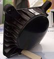
Doppler radar antenna for use in vehicles

Storm front on a Doppler radar screen

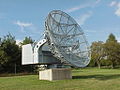
Hooksielplate radar tower, equipped with radar and direction finding systems, is part of the Jade and German Bight shipping traffic safety system
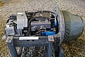
On-board radar RP-21 Sapfir of a MiG-21


.jpg)
Classification and functionality


Active radar devices are divided into imaging and non-imaging . Furthermore, a distinction is made between pulse and continuous wave radar devices and between mono and bistatic systems; with the latter, the transmitter and receiver are spatially separated, which allows greater sensitivity at an astronomical distance. Radar transmitters can be identified and located using direction finders.
Pulse radar devices are referred to as primary radar, which only evaluate the passively reflected echo of the target. In addition to the distance, the radial speed of the objects and their approximate size can also be determined. Evaluation of reflected harmonics allows conclusions to be drawn about the type of aircraft.
A secondary radar also includes a pulse radar device, but there are transponders on the target objects which react to the pulses and in turn send back a signal. This increases the range, the objects are identifiable and can send back further data if necessary.
Directional receivers that can locate the source of radio waves (from radar and other devices and their radiated interference) for military purposes are also called passive radar . A passive radar cannot therefore be detected based on its radio wave emission.
Another type of radar that is difficult to detect is noise radar, which emits long pulses that look like random interference.
Pulse radar
Distance determination with the pulse method

A pulse radar device sends pulses with a typical duration in the lower microsecond range and then waits for echoes. The duration of the pulse is the time between sending and receiving the echo. It is used to determine the distance. The following applies to the distance :


The group speed is approximately equal to the speed of light in a vacuum because the refractive index of air for radio waves is very close to 1. Depending on the range of the radar device, a transmitted pulse is received for a few microseconds to milliseconds before the next pulse is transmitted.

On the classic radar screen , the deflection begins with the transmission pulse. The speed of propagation of the electromagnetic waves in space is to scale with the display. If an echo is received, the distance between the echo pulse on the viewing device is a measure of the distance between the reflecting object (here: the aircraft) and the radar device.
Pulse generation
In order to generate the high transmission powers in the megawatt range in pulse radar devices, which are used for locating z. B. are necessary over a few 100 km, magnetrons are still used today. For this purpose, a magnetron z. B. pulsed by means of Trigatron , Thyratron or, recently, semiconductor switches.
Since the transmission frequency of a magnetron can change as a function of temperature and operating condition, the frequency reference is derived from the transmission frequency when measuring the relative radial velocity (see pseudo-coherent radar ).
Stationary pulse radar devices achieved outputs of up to 100 MW as peak pulse output. Modern radar devices require much less energy for ranges of several 100 km and sometimes send pulses with a pulse power of less than one megawatt.
When using a large number of small, networked transmitters or devices with active phased array antennas , the X-ray switching tubes can be dispensed with.
Direction determination
If you turn the antenna of a pulse radar, you get a panoramic radar . The sharp directional characteristic of the antenna is effective both when transmitting and receiving. The direction can be determined very precisely from the dependence of the strength of the echo on the orientation of the antenna. The best-known areas of application for such a panoramic radar are air surveillance and weather radar .
An airport surveillance radar (ASR, Airport Surveillance Radar ) usually combines a primary radar with a secondary radar . In addition to general airspace surveillance, its main task is to provide the approach controller with an accurate picture of the air situation around the airport. The range of an ASR is usually 60 nm .
An approach radar consists of a horizontally and a vertically moving antenna and enables the approach angle, approach direction and approach altitude of landing aircraft to be determined. The pilot receives the correction information by radio from the ground crew or he has a display instrument on board that passively indicates deviations based on the received radar pulses. Such instrument landings or blind landings are particularly important in poor visibility or if the runway is unfired or camouflaged for military reasons. However, a view of the ground is required shortly before touchdown.
The ground-based STCA (Short Term Conflict Alert) system for collision avoidance uses the air surveillance radar. From the flight path of aircraft, it calculates the probability of a near miss or even a collision and warns the air traffic controller visually and acoustically .
The swiveling of the scanning beam of a pulse radar can also be effected electronically by phased antenna arrays instead of by aligning the antenna . This means that several objects can be targeted in quick succession and followed virtually simultaneously.
The Synthetic Aperture Radar achieves a high, distance-independent resolution in azimuth . The required aperture size is computationally composed of the real aperture of a small, moving antenna. For this, the movement of the antenna relative to the observed (rigid) object must be known exactly and the phase of the transmitted pulses must be coherent with one another. Earth satellites and space probes use such systems to measure terrain profiles.
Radar assemblies in pulse radar
Radar antennas


The antenna is one of the most noticeable parts of the radar system. The antenna ensures the necessary distribution of the transmission power in the room by means of the antenna diagram and, if necessary, a rotary movement. The antenna is mostly used in time division multiplexing. During the reception time, it then receives the reflected energy.
The antenna pattern has to bundle very strongly so that a good lateral and vertical resolution is achieved. The distance resolution, however, is determined by the pulse duration. In the case of mechanical space scanning, the antenna is rotated or swiveled back and forth. This movement can cause a considerable mechanical problem because the antenna reflectors reach very large dimensions with large wavelengths or high focusing. The following antenna designs are common for radar devices:
- Passive phased array antennas (see also group antenna , panel antenna )
- Active Electronically Scanned Array (AESA), as above, but with active electronic control of the individual elements, electronic beam pivoting, target tracking
- Parabolic antennas
More modern radar devices with multifunctional properties always use a phased array antenna, older device systems usually use the parabolic antenna, which deviates from the ideal parabolic shape to generate a cosecans² diagram .
Radar transmitter
One type of transmitter used in older radars, but also used today, are self-oscillating pulse oscillators, which consist of a magnetron . The magnetron is fed by a high-voltage pulse and generates a high-frequency pulse of high power (0.1 ... 10 µs, power from a few kW to a few MW). The high-voltage pulse for the magnetron is provided by a modulator (switch tube or, today, semiconductor switch with MOSFET ). This transmission system is also POT ( P ower- O szillator- T called ransmitter). Radars with a POT are either incoherent or pseudo-coherent .
A solvent used in modern radar equipment concept is the PAT ( P ower- A mplifier- T ransmitter). With this transmitter system, the finished transmission pulse is generated with low power in a generator and then brought to the required power with a high-performance amplifier ( Amplitron , Klystron , traveling wave tube or semiconductor transmitter modules). Radar devices with a PAT are in most cases fully coherent and can therefore be used particularly well for detecting moving objects by using the Doppler frequency .
receiver
The receiver mostly uses the transmitting antenna and must therefore be protected from the transmission pulse. This is done with circulators , directional couplers and nullodes . Reception is based on the superposition principle . In the past, a reflex klystron was used as an oscillator , and coaxially constructed tip diodes screwed into the waveguide were used for mixing and demodulation . Today's receivers work entirely with semiconductors and are constructed using stripline technology.
Continuous wave radar (CW radar)
A CW radar (CW for continuous wave ) of constant frequency cannot measure distances, but the azimuth to a target via the directivity of its antenna . It is used to measure speed . The frequency emitted by an antenna is reflected by the target (for example a car) and received again with a certain Doppler shift , i.e. slightly changed. Since only moving objects are recognized, there are no disruptive influences from fixed targets. By comparing the transmitted frequency with the received frequency ( homodyne detection ), the radial speed component can be determined, which is a cosine factor smaller than the magnitude of the speed vector.
- Speed sensors based on this principle are used on rail vehicles; they radiate diagonally into the track bed. The required transmission power is very low and is often generated with Gunn diodes .
- The first radar devices of the traffic police were also continuous wave radar devices. Since they could not measure a distance, they were not yet working automatically.
- Anti-aircraft radars with Doppler detection radar, such as the AN / MPQ-55 (CWAR), recognize their target even in the event of severe chaff interference.
- Radar motion detectors also work according to this principle, but they must also be able to register slow changes in the received field strength due to changing interference conditions.
Modulated continuous wave radar (FMCW radar)

A further developed type are the FMCW (frequency modulated continuous wave) radar devices , also modulated CW radar or FM radar. They transmit at a constantly changing frequency. The frequency either rises linearly in order to abruptly fall back to the starting value at a certain value (sawtooth pattern), or it rises and falls alternately with a constant rate of change. Due to the linear change in frequency and the constant transmission, it is possible to determine the absolute distance between the transmitter and the object as well as the speed difference between them. Radar traps used by the traffic police work in this way and trigger the photo flash if the speed is exceeded at a certain distance from the target. Radar altimeters in aircraft and distance warning devices in cars work on this principle. This technology is also used for panoramic radar in the marine area (broadband radar). It is not possible to use this broadband radar for air reconnaissance because the Doppler frequency of aircraft is too high and this results in measurement errors of up to several kilometers. The reason for this is the sawtooth-shaped modulation used, because of which the broadband radar cannot distinguish between the frequency difference caused by the transit time and the frequency difference caused by the Doppler effect.
FMCW radars are also used in industrial applications to measure distance and level in tanks.
Health damage from radar
The X-rays generated in the interrupter were often inadequately shielded in military radar systems until at least the 1980s. In addition, maintenance and adjustment work often had to be carried out on the open device. This led to radiation damage to many service and maintenance soldiers in the NVA and the Bundeswehr . A large number of soldiers, especially former radar technicians, later developed cancer as a result , and many died at a relatively young age. The number of victims ( radar victims ) is several thousand. In principle, the connection was recognized by the Bundeswehr and in many cases an additional pension was paid.
See also
literature
- David K. Barton (Ed.): Radar evaluation handbook. Artech House, Boston MA 1991, ISBN 0-89006-488-1 , ( Artech House radar library ).
- Guy Kouemou (Ed.): Radar Technology. InTech, 2010, ISBN 978-953-307-029-2 , (online)
- Albrecht Ludloff: Practical knowledge of radar and radar signal processing (= Viewegs technical books on technology ). 3rd, revised and expanded edition. Vieweg Verlag, Braunschweig 2002, ISBN 3-528-26568-X .
- Albrecht Ludloff: practical knowledge of radar and radar signal processing (= practice: information and communication technology ). 4th, revised and expanded edition. Vieweg Verlag, Braunschweig 2008, ISBN 978-3-8348-0597-3 .
- Jakov D. Schirman: Theoretical basics of radio location. Military publishing house of the GDR, Berlin 1977.
- Merill I. Skolnik (Ed.): Radar Handbook . 3. Edition. Mcgraw-Hill Professional, New York NY 2008, ISBN 978-0-07-148547-0 .
Web links
- Basics of radar technology on radartutorial.eu
- The history of the radar on 100-jahre-radar.de
- Fraunhofer Institute for High Frequency Physics and Radar Technology FHR
- Space observation radar TIRA (Tracking and Imaging Radar) from Fraunhofer FHR
- DLR Institute for High Frequency Technology and Radar Systems
Individual evidence
- ^ The indirect distance measurement with radar , Pionier, Zeitschrift für Transmission Troops, Number 1, January 1949
- ↑ Ekbert Hering , Rolf Martin: Optics for engineers and natural scientists: Fundamentals and applications . Carl Hanser Verlag, 2017, ISBN 3-446-44509-9
- ↑ Eugene Hecht : Optics 4th edition. Oldenbourg, Munich 2005, ISBN 3-486-27359-0
- ↑ www.radarpages.co.uk
- ↑ Peter Volk: Radio navigation - Radar yesterday and today. In: seefunknetz.de. 2005, accessed February 28, 2015 .
- ↑ Broadband Radar on simrad-yachting.com
- ^ R. Timothy Hitchcock, Robert M. Patterson: Radio-Frequency and ELF Electromagnetic Energies: A Handbook for Health Professionals . Wiley, 1950, ISBN 0-471-28454-8 , limited preview in Google Book Search.