Active Electronically Scanned Array
The active electronically scanned array ( AESA ), also known as active phased array -Radar forms a radar system with an active electronic scanning . Its function is based on many individual, small transmit / receive modules .
The alignment and bundling of the antenna diagram to determine the direction is carried out as with passive phased array radar systems (PESA systems) by the phase shift between the individual modules on the antenna surface. A difference in distance between a source and the elements in the order of magnitude of a wavelength, as well as their phase shift, result in preferred directions due to interference (physics) . An AESA radar therefore has the same properties and advantages as a passive phased array radar. The difference is that here each module has its own power amplifier and often its own RF generator, while the passive variant uses a common RF source, the signal of which is modified by digitally controlled phase-shift modules. The feed lines and power dividers from a central transmitter block to the individual phase shifters and individual radiators are not required in AESA systems, which means that they are more compact. The circuitry effort is, however, greater overall at AESA.
In multi-function radar devices, a different form of the antenna diagram is formed at the moment of transmission than at the time of reception. In the case of transmission, the entire area to be covered must be illuminated with transmission energy at the same time. During the reception time, various narrower antenna diagrams are distributed in different directions. Therefore, the phase shifters used in the antenna upstream of the power amplifiers are not also used for the receivers at the same time. In modern multifunctional radar devices, the phase shifts required for the receiving channel are even carried out digitally in a special processor for antenna diagram formation ( digital beamforming , DBF).
Use in aircraft


Compared to classic radar systems, a phased array system is basically mechanically simpler. It does not need servomotors to swivel the radar lobe to side or elevation, nor hinges or other parts that can be prone to failure. It therefore also requires less space, which is advantageous in air-supported systems. Furthermore, the maintenance of the radars is easier, while at the same time increasing reliability: Up to 10% of the AESA modules can fail without significantly impairing their function. If, on the other hand, the traveling wave tube fails with a mechanically controlled or PESA radar, the radar fails completely.
When used in combat aircraft , the advantages over conventional radar are:
- High speed of a "radar beam passage", but limited by the signal propagation time.
- Long range in a straight line of sight, sloping with increasing swivel angle because the effective antenna area decreases.
- Several goals can be pursued at the same time.
- Overall lower transmission power, thus lower probability of being discovered.
- Can be used as a jammer ( jamming ).
- Increased reliability, several modules can fail without impairing functionality.
Advantages over the passive PESA variant are increased reliability and service life of the components, since among other things no high voltages or traveling wave tubes are required and the radar is lighter. Another advantage is the simultaneous transmission on different frequencies, which makes electronic countermeasures more difficult and enables better LPI properties. However, current airborne radars are limited by their design to a small number of transmission and reception channels with different frequencies. This process also significantly reduces the range. Further disadvantages are the need to be installed at an angle, otherwise the frontal radar cross-section increases , and AESA systems have a limited field of view of a maximum of ± 60 ° in both vertical and horizontal directions.
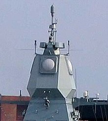
To the field of view of max. To increase ± 60 degrees and improve the inadequate focus in the edge area, it makes sense to also build a movable AESA radar. The mechanics can be simpler than with classic systems, since they only have to roughly pursue a goal. In fixed installations where weight and volume play a subordinate role, such as on aircraft carriers and frigates, each direction is assigned a rigid flat antenna; this also avoids weather influences on rotating radar dishes.
List of AESA radars

Airborne systems
- AN / APG-63 (V) 2 in the F-15C Eagle (introduced in 2000 as the first operational AESA radar in the world)
- AN / APG-63 (V) 3 for the F-15C and F-15SG; 2006 in the prototype stage
- AN / APG-70 in the F-15E Strike Eagle
- AN / APG-77 in the F-22 Raptor
- AN / APG-79 in the F / A-18E / F Super Hornet
- AN / APG-80 in the F-16E / F Block 60 Fighting Falcon
- AN / APG-81 in the F-35 Lightning II
- AN / APG-82 (originally named AN / APG-63 (V) 4) as an upgrade for the F-15E Strike Eagle and the F-15SE Silent Eagle
- AN / APQ-181 (AESA upgrade currently in development), in the B-2 stealth bomber
- BAE Systems Seaspray 7000E, in helicopters
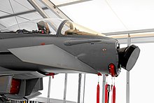
- Captor-E for the Eurofighter Typhoon
- Ericsson Erieye AEW & C and NORA AESA in the Saab 39 Gripen
- Fasotron Schuk-AE in the MiG-35
- IAI Phalcon AEW & C Elta radar system
- Mitsubishi Electric J / APG-1 AESA in the Mitsubishi F-2 fighter aircraft
- Northrop Grumman SABR , for F-16 Fighting Falcon upgrades
- RBE2-AA ordered for the Dassault-Rafale fighter aircraft from the fourth tranche (to be delivered from 2012 in the F3 standard).
Ground and sea based systems
- APAR ( Active Phased Array Radar ) ship-based multifunction radar
- IAI EL / M-2080 "Green Pine", ground-based early warning AESA radar ( Memento from May 30, 2009 in the Internet Archive )
- Sea-Based X-Band Radar to track intercontinental ballistic missiles
- AN / TPY-2 for the THAAD system
- AN / SPY-3 for the Zumwalt- class , Gerald R. Ford- class, and CG (X) (next generation warships)
- SAMPSON for the Daring class and Queen Elizabeth class
Individual evidence
- ↑ Phased Array Antennas
- ↑ Digital beamforming on the radar tutorial
- ↑ The antenna area decreases with the swivel angle and an increase in unwanted side lobes
- ↑ Physical limits of electronic beam swiveling ( Memento from April 12, 2008 in the Internet Archive )
- ↑ thefreelibrary.com - Fighters face the Aesa revolution , 2007. Access January 21, 2009
