
Klystron

The klystron is an electron tube that uses the transit time of the electrons to generate or amplify high-frequency signals ( transit time tube ). The basic principle was published by Oskar Heil in 1935. It was developed in 1937 by the Russell and Sigurd Varian brothers with the assistance of William Webster Hansen at Stanford University (California).
In the klystron, a stream of electrons generated in a vacuum and accelerated by high voltage experiences a speed modulation by a high-frequency alternating electric field . To do this, it passes through a cavity resonator fed with a high-frequency signal . After a certain running time, the speed modulation effects a density modulation. The modulated electron stream can be passed through one or more further cavity resonators (multi-chamber klystron), and part of its energy can be extracted from the last resonator as high-frequency energy.
Two-chamber klystron

This amplifier for very high frequencies is not used in practice, but is well suited for describing the basic mode of action of a klystron. The high-frequency part is formed by two cavity resonators: In the first cavity resonator (control chamber, coupling resonator) an electromagnetic oscillation is excited by the signal fed in, the electrical component of which in the center of the resonator interacts with the electron beam and modulates its speed (alternately by acceleration and braking, depending on the phase in which the controlling signal is). The faster electrons can now overtake the slower electrons that were sent out earlier. After a certain running time, braked, unaffected and accelerated electrons are in the same place, creating an electron packet ( bunch , density modulation). Due to the ongoing differences in speed, this packet dissolves again, only to be formed again later. This means that the density-modulated points repeat periodically along the path of the electrons; a space charge wave is created .
In the two-chamber klystron, the center of the second cavity resonator (decoupling resonator) is at the first maximum of the density modulation. By induction wall currents caused in the second cavity resonator, the cavity is formed an electro-magnetic vibration, the electrical component is directed so that it brakes the electron bunches. As a result, the electron beam transfers part of its kinetic energy to the electromagnetic field. A portion of its energy can in turn be extracted. As a result of the energy transfer from the electron beam, the coupled out wave has a greater amplitude than the coupled one, so the two-chamber klystron works as an amplifier.
The electron beam is then collected by a collector.
Multi-chamber klystron

For the output powers required in practice, high power electron beams are required. The resulting high space charge density in the beam requires modulation at high speed due to the Coulomb forces between the electrons to form a packet. This is achieved by using additional resonators (intermediate resonators) between the input and output resonator. Since normally no power is extracted from them, higher electrical fields develop in them in a cascading manner in the resonator centers, which ultimately lead to the required packet formation. At the same time, the method has the advantage that by detuning the resonance frequencies of the intermediate resonators against each other, a significantly higher bandwidth (up to approx. 1%) can be achieved compared to the two-chamber klystron.
Amplifier klystrons can be built as multi-chamber klystrons for short pulse outputs (microsecond range) up to around 100 megawatts, in continuous operation ("continuous wave output") up to well over 1 megawatt. The frequency range extends from a few 100 MHz to a few 10 GHz.
Typical areas of application are strong UHF and microwave transmitters, radar (reflex klystron as a mixed oscillator), microwave heating (e.g. in chipboard production), medical and scientific particle accelerators and broadband satellite communication .
Until a few years ago, the klystron was widely used in terrestrial UHF transmitters. In the meantime, however, it is being replaced more and more by IOT (Inductive Output Tube) or by semiconductor amplifiers.
Reflex klystron

With the reflex klystron, also known as the Sutton tube , the modulating and the withdrawing cavity are identical - the electron flow is reflected in these by a negatively biased electrode. The reflex klystron can therefore act as an oscillator . The name Sutton tube is derived from its inventor Robert Sutton, who developed this type of tube in 1940. Reflex klystrons were used in what was then the first radar equipment during World War II , but were soon replaced by the magnetron on the British side . The reflex klystron was now only used as a mixer oscillator in the receiving branch of the devices and for radio relay purposes. In the 1960s, the reflex klystron and smaller pulse sources were replaced in many areas of application by Gunn diodes , which are considerably smaller, more adjustable and more efficient and work with only one and also lower operating voltage.
Until the 1980s, reflex klystrons were used on a large scale (e.g. the TK6 from Telefunken for 7 GHz) in radio relay systems.
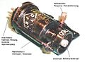
The functioning of the reflex klystron is explained with the help of the picture on the right: Some of the electrons that are emitted by the hot cathode and accelerated by the anode pass through the resonator chamber and generate a weak electromagnetic field in it through influence. After a certain running time they are forced to reverse by the negative electrical potential of the reflector and pass through the resonator chamber in the opposite direction. If at this point in time the previously induced current direction has just reversed in this resonant circuit , this oscillation is amplified again, an oscillator is created. Part of the generated HF energy can be inductively coupled out through a wire. Since most of the electrons that are emitted by the cathode land directly on the anode, the efficiency is only a few percent. The decisive factor for the function is a sufficient correspondence of the electron transit time with a multiple of the oscillation period. A frequency modulation is achieved by changing the reflector voltage slightly . The frequency can often be changed or adjusted by mechanically deforming the resonator.
Furthermore, there are makeshift solutions on how to operate a conventional multigrid tube as a reflex klystron by attaching an external resonator to two of the grids, e.g. B. a Lecher line , connects and uses the anode as a reflector. This is also known as the Gill-Morell vibration and was investigated as early as the beginning of the 20th century. For this see Barkhausen-Kurz oscillation .
Reflex klystron approx. 9 GHz, mechanically tunable, length approx. 70 mm, Soviet Union approx. 1966 (replica Raytheon 2K25)
Reflex klystron for connecting an external resonator (type K-11, Soviet Union 1963)

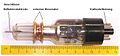
Reflex Klystron from Raytheon, USA
Cut-open reflex klystron with waveguide decoupling


See also
literature
- Klaus Wille: Physics of particle accelerators and synchrotron radiation sources . An introduction. Springer, 2013, ISBN 978-3-663-11850-3 ( limited preview in Google book search).
Web links
- radartutorial.eu: Functional description of the klystron
Individual evidence
- ^ Paul A. Redhead: The Invention of the Cavity Magnetron and its Introduction into Canada and the USA. La Physique Au Canada, 2001, archived from the original on October 9, 2014 ; accessed on June 9, 2019 .
- ↑ Telefunken tubes and semiconductor messages: The Telefunken-Reflex-Klystron TK 6
- ↑ http://www.elektronik-labor.de/Notizen/reflexklystron.pdf “HF pentode as reflex klystron” in Funkschau 1969 issue 11 page 974