
Circulator
A circulator is a component or circuit for separating signal directions. One differentiates:
- passive components of the high and very high-frequency technology with usually three terminals (ports), which is similar to a Faraday rotator function
- active circuits made up of operational amplifiers (so-called active circulators) for low signal frequencies; such circulators can have different numbers of inputs and outputs.

A signal that is fed into one of the ports is passed on to the next port. At an open port it is forwarded unchanged, at a short-circuited port the sign of the signal voltage is reversed. If the connection is completed with the correct impedance , the signal is not forwarded to the next port. The signals are passed on “in a circle”, hence the name circulator .
Active low frequency circulators


An active circulator for low frequency made up of discrete electronic components consists of several identically structured stages with an operational amplifier with one port each. At a port that is not connected, the input signal of a stage is forwarded unchanged to the output . If the port is connected to ground , the voltage of the signal is inverted. If a resistor R with the amount to ground is connected to the port , the voltage of the signal is applied to R and the signal is not forwarded to the next connection.


functionality
The function of the 3-port circulator shown in the figure is described in more detail below. Since the outputs of the individual stages are connected to the inputs of the following stages, the following applies:


If you apply the voltage U 1 to ground at connection 1 , connect the resistor R = R g to ground at connection 2 and leave it open at connection 3, the mode of operation can be demonstrated. The output voltage U a2 of the operational amplifier N 2 becomes zero. The stage of the operational amplifier N 3 has a gain of 1, since the connection is not connected, as a result of which U a3 = U e3 = U a2 . The amplifier stage N 1 works as an electrometer amplifier with a gain of 2, which means that the output voltage U a1 has an amount of 2 · U 1 . At connection 2, half of the output voltage U a1 drops across resistor R , which corresponds to the amount of U 1 .
For the calculation of intermediate values of these extremes, the knot rule is applied to the N and P inputs of the operational amplifiers. This results in the following equations:
| step | P inputs | N inputs |
|---|---|---|
| N 1 | ||
| N 2 | ||
| N 3 |


Construction with power sources
.svg)
From the equations shown above, the following equations are obtained by eliminating the input and output voltages:


From these equations it can be seen that the currents are dependent on the voltages. A circulator can therefore also be constructed from voltage-controlled current sources with differential inputs. These are mainly built from CC operational amplifiers , which are particularly suitable for this purpose. The figure shows the structure of a voltage-controlled current source . The current I a at the output is given by the equation

given. The input voltage U e can be generated with the aid of an analog subtracter .
Hybrid circuit

An example of circulators is the telephone hybrid . This consists of a circulator with three ports, which is terminated with the circulator resistance R g (which is selected depending on the type of conductor used). The signal from the microphone is sent to the exchange, but does not reach the loudspeaker (receiver). Conversely, the signal coming from the exchange is transmitted to the loudspeaker, but does not reach the microphone. The crosstalk attenuation is mainly determined by the pairing tolerance of the terminating resistors. A transformer is used to rotate the phase in historical telephones .
High frequency circulators


Ferrite circulators
Circulators of high frequency technology (UHF to microwaves) are currently being implemented with Faraday rotators made of ferrites in waveguide or stripline technology. In stripline technology, for. B. an annular conductor loop or circular area surrounded by a soft magnetic ferrite material . The yoke of a permanent magnet , which premagnetizes the ferrite , is arranged perpendicular to it . On the ring or circular conductor, three connections (ports) are attached at an angle of 120 ° to each other, which are used to couple the signals.
Such circulators are often designed as flat, approx. 30 ... 50 mm large, round or rectangular components, which, provided with three coaxial sockets, are usually housed in RF-tight housings. There are also miniature circulators for installation in printed stripline circuits. Waveguide circulators are used for very high frequencies and powers, e.g. B. on radars used.
Electrical Properties
The transmission loss of passive HF circulators is usually well below 1 dB , while the attenuation in the reverse direction - assuming a correct adjustment - is over 20 dB. The desired function is frequency dependent, i. That is, a circulator can only be used within the specified frequency range. The bandwidth is, for example, 10%. In the waveguide version, HF continuous power (CW) or over 50 MW can be transmitted in a pulsed manner over 1 MW .
Ideal scatter matrix :

Working principle
The function of a circulator is that the energy at the input (port 1) is initially separated into two equal parts, which, however, get a different speed of propagation due to the ferrite. Both halves of the signal are in phase opposition at port 3, so they cancel each other out. Both halves of the signal are in phase at port 2, so they add up again to form the complete signal.
Due to the symmetrical structure of the ferrite circulator, it is possible to always determine a defined path direction by selecting the connection. If there is an antenna at port 3, the transmission energy is always directed from port 2 to the antenna, while the echo signals always find their way to the receiver at port 1.
The behavior of a circulator is non-reciprocal; This means that the transmission from port 1 to port 2 does not correspond to the transmission in the opposite direction. This is achieved by using materials (ferrite in a constant magnetic field ) whose permeability depends on the direction of the field. The behavior of ferrite is anisotropic and can be described as a skew-symmetric tensor (polder tensor). The electron spin and the precession of the atoms within the ferrite when a magnetic field is applied play a role.
Series of images: Disassembly of a ferrite circulator

A ferrite circulator for about 1GHz ...

... the circulator is surrounded by two powerful permanent magnets under the housing ...
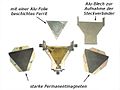
... a ferrite layer under each magnet and the line structure with the connections in the middle.


Special forms

If a terminating resistor (dummy) is permanently connected to one of the three ports of a ferrite circulator , signals can only be passed on to the remaining two ports in one direction. In the other direction the signals are strongly attenuated. Because of this property, this version is called an isolator . They are used to suppress reflected waves in the antenna cables of radio or microwave transmitters. A missing or incorrectly connected antenna would otherwise lead to an unfavorable mismatch of the transmitter.
Based on the same principle of Faraday rotators, there are also isolators for optical wavelengths, which make it possible to decouple signals as a function of polarization.
Optical circulators and isolators are used in communications technology in WDM systems , fiber amplifiers or in OTDR measurement technology, for example to minimize crosstalk.
application
Ferrite circulators are often used as duplexers in radars ; i.e., to decouple sent signals from received signals. In wireless technology and radar technology ferrite circulators are used.
For example, an incoming signal from the antenna at port 1 is passed on to a receiver at port 2. However, the RF power of a transmitter on port 3 can only reach the antenna (port 1). The transmission power at port 3 cannot go backwards to the receiver at port 2 - the receiver is thereby protected and no signal power is lost. This means that the same antenna can be used simultaneously for sending and receiving. A correct impedance connection of all three ports is a prerequisite for proper function.
Integrated HF circulators
Due to the poor miniaturization and integration ability of ferrite circulators as well as their required magnetic field, there have been efforts for a long time to integrate such non-reciprocal circuits also for maximum frequency or to realize them fully electronically. For this purpose parametric delay line pairs operated by synchronous switches are used. This is the first time that a broadband (30 GHz) ferrite-free and magnetic field-free circulator has been created that can be integrated - it is built using monolithic CMOS silicon technology. However, such circulators can only be used with comparatively low powers.
See also
Web links
Individual evidence
- ↑ https://www.nature.com/articles/s41467-017-00798-9#Fig3 Tolga Dinc, Mykhailo Tymchenko, Aravind Nagulu, Dimitrios Sounas, Andrea Alu, Harish Krishnaswamy: Synchronized conductivity modulation to realize broadband lossless magnetic-free non-reciprocity in Nature Communications 8 , Article 795, Oct. 6, 2017, accessed Oct. 12, 2017