Waveguide
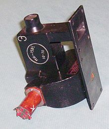
A waveguide is a waveguide for electromagnetic waves primarily in the frequency range from 1 GHz to 500 GHz. Waveguides are metal tubes with mostly rectangular, circular or elliptical cross-sections. With them, electrical power in the frequency range mentioned can be transmitted with much less loss than with electrical cables such as coaxial cables . Due to their construction, waveguides are preferred for high power or very high frequencies, as there is no need for a conductive center conductor as with a coaxial cable. Since a waveguide can practically only be made of metal such as brass, it is particularly robust against environmental influences, extreme temperatures, vibration or space radiation and is therefore widely used in aerospace, as well as stationary transmission systems on land and on ships.
Physical background
If an electromagnetic wave hits a highly conductive interface, it is reflected in itself. With a suitable distance between a parallel second interface, a standing wave is formed . If side walls are added, a cavity resonator is created . In this, too, the electromagnetic waves are standing waves; it is a stationary electrical and magnetic alternating field . The possible resonance frequencies of the standing waves depend on the distance between the walls.
In a waveguide, on the other hand, the alternating electric and magnetic fields move:
Imagine a long tube with a rectangular cross-section in which a plane wave hits a narrow side perpendicularly and is reflected back and forth between the two walls. The wavelength is twice as large as the distance between the two walls, so that a standing wave is created. If the distance between the two walls is reduced a little, the wave can only propagate at a special angle at which a standing wave again arises between the two walls. To do this, the wavelength along the longer wall must be twice as large as the distance between the two walls. The resulting wavelength in the longitudinal direction leads to wave propagation along the waveguide. To distinguish between standing waves, one speaks of a traveling wave .
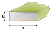
The minimum width of a rectangular waveguide corresponds approximately to half the wavelength of the transmitted frequency - precisely then only a single antinode fits into it in the transverse direction. One can therefore deduce the lowest frequency used in the associated device from the width of a rectangular waveguide. The associated wavelength is called the critical wavelength λ k or the cut-off wavelength λ c (with c for “cut-off”). It is calculated according to the relationship λ k = 2 · a (where a is the longer side of the rectangular waveguide cross-section, see sketch above). By expanding the waveguide filter , specific frequency ranges can be suppressed in a targeted manner.
Waveguides can also be operated with increased internal gas pressure in order to be able to transmit higher powers (in accordance with Paschen's law ) without flashovers or air breakdowns occurring. In this context, the phenomenon of multipaction means the constructive superposition of several different wavelengths, which can result in very high field strengths.
Fashions
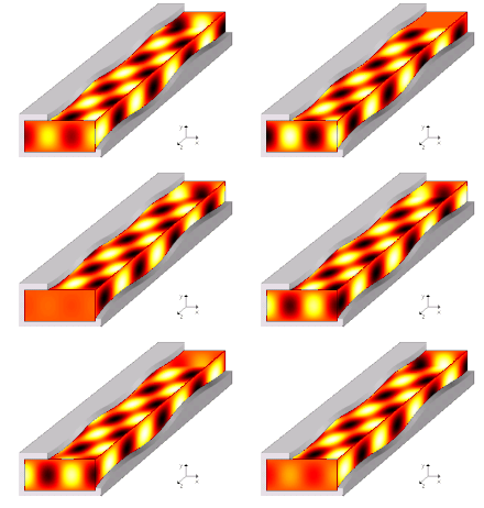
The type of propagation described can take place in such a way that an integral multiple of half the wavelength fits between the narrow sides. The various possible states are the so-called oscillation modes, modes for short, and are denoted by the numbers that correspond to this multiple; so: 1, 2, 3,….
At higher frequencies, the horizontal transversal modes are joined by the vertical ones between the top and bottom of the pipe, where different modes occur independently. Therefore, to describe a mode in a rectangular waveguide, it is necessary to specify two numbers, the mode order : z. B. (2,3) mode . One of the numbers stands for one of the transversal modes in the direction of the electric and magnetic field components (E and H direction).
The field lines of the electric field are always perpendicular to the outer conductor and run from one wall side to the other. Depending on how many extreme values the field course has over the entire width of the waveguide, the mode designation receives its first index. The width of a waveguide is denoted by a. With a maximum, the minimum number for the electrical field distribution, one speaks of a - or wave.
Similarly, the number of maxima in the course of the electric field over the entire height of the waveguide denotes the second index. The height of a waveguide is denoted by b. The field strength can be over the entire height of the waveguide are constant (it must therefore be no maximum), this is called a or shaft.
There are also comparable modes in round waveguides. Here, however, there are also modes that have a homogeneous field distribution along the pipe circumference.
The coupling and decoupling of the HF energy takes place through slots, coupling loops, rods, funnels (horn radiators) or holes - depending on whether the energy should get into another waveguide, into a coaxial cable or into the open. The location and shape of these coupling elements determine the mode and direction of propagation of the waves.
E / H modes
In electromagnetic waves, the electric and magnetic fields are always perpendicular to one another. So that the wave can propagate in one spatial direction, wave components must exist in this spatial direction. If the electric field is perpendicular to the direction of propagation, one speaks of H-modes. If the magnetic field is perpendicular to the direction of propagation, one speaks of E-modes. The figure shows a longitudinal section through a waveguide (z-direction).
Waveguide wavelength and cutoff frequency
While the distance between the maxima of the field distribution in the x or y direction depends on the free space wavelength of the wave, the waveguide wavelength is decisive for the distance between the maxima in the z direction, i.e. in the direction of propagation .
The waveguide wavelength depends according to the above equation from the mode order, the free space wavelength and of width and height of the waveguide from, but not whether the mode is electrically or magnetically. It is always greater than the free space wavelength of the same frequency and the phase velocity in the z-direction is correspondingly greater than the speed of light.
The relationship is non-linear, and for a given mode order and dimensions there is a free space wavelength for which the waveguide wavelength approaches infinity:
A diverging waveguide wavelength means that the wave cannot propagate (group velocity zero). Since the waveguide wavelength for a mode of a certain frequency depends on the dimensions of the waveguide, not any modes can propagate in a waveguide. The higher the value of a mode, the greater its cutoff frequency or the smaller the cutoff wavelength .
The cutoff frequency divides the frequency range into two ranges, the attenuation range and the propagation range. The decisive factor here is the behavior of the propagation coefficient γ over the frequency.
The wave cannot propagate in the attenuation area. The coefficient of dispersion is purely real. The wave is accordingly dampened aperiodically. Modes that are not capable of propagation can be excited and at least temporarily bind part of the wave energy. If the frequency of the wave is the same as the cut-off frequency, the propagation coefficient is zero. The wave is reflected at a right angle between the sides of the waveguide without any energy transport taking place.
The wave is capable of propagation for frequencies above the cutoff frequency. The expansion coefficient is ideally and therefore purely imaginary. The wave is therefore not damped, but propagates in the waveguide with a frequency-dependent phase shift . A wave capable of propagation is also damped in the real waveguide. The losses in the waveguide wall (surface currents), which is only finely conductive, contribute to this. The (loss) share of the surface currents in the power transport is mode-dependent, tends to decrease with higher modes and tends to increase due to the skin effect . Since waveguides are usually filled with air or gas, there are no dielectric losses. This is an essential factor for their use at very high frequencies.
Wave impedance
The wave impedance links the amplitudes of the electric and magnetic field strengths of an electromagnetic wave. In the waveguide it is frequency-dependent and differs for TM and TE mode, but has the same value everywhere in the waveguide.
where f limit means the cut-off frequency of the respective mode and is the free space wave resistance .
Above the cutoff frequency ( f > f limit ) the impedance is real and energy is propagated in the waveguide. Below the cutoff frequency, on the other hand, the impedance is imaginary and the wave penetrates the waveguide with decreasing amplitude.
Different waveguides and their modes
Many characteristic properties are common to all waveguide types. This includes a cut-off frequency below which no wave propagation takes place.
While TEM waves propagate in a coaxial cable (electric and magnetic fields are always perpendicular to the direction of propagation), only so-called H waves (also TE waves) and E waves (TM waves) are found in a waveguide magnetic or the electric field components in the direction of propagation.
Waveguides have a high-pass behavior , with a cutoff frequency. Rectangular and circular waveguides show the basic wave types mentioned below. If these fundamental waves (in relation to H or E waves) have no way of propagating due to the dimensions of the waveguide, no other wave types will propagate either. See also cavity resonator . Above the cut-off frequency, the propagation of the waves ( e.g. group speed , phase speed and wavelength) depends on the frequency. The wave propagation in the waveguide is therefore in principle dispersive .
The following rules apply to the existence of fashions:
- Electric and magnetic field lines are always perpendicular to one another.
- Magnetic field lines are always closed and cannot hit walls - they can only touch walls.
- Electric field lines cannot appear along the walls, but only hit them perpendicularly.
Rectangular waveguide

As already mentioned above, the largest dimension is decisive for a rectangular waveguide. This means that the width determines the waves that can propagate in this conductor.
The following applies to the E-wave in the direction of propagation:
where m and n represent the mode numbers ( m : x-direction (transverse) and n : y-direction (vertical) with respect to propagation in the longitudinal direction z). a is the larger dimension of the waveguide. See also Maxwell's equations .
It follows from this that the fundamental wave type of the E-waves is the -wave, since the above equation with the values m = 0 or n = 0 leads to and therefore no E-component exists in the direction of propagation. Thus, at least -waves must be able to arise in the direction of propagation in the rectangular waveguide .
However, the H10 wave is typical for rectangular waveguides.
Round waveguide
For the circular waveguide, the oscillation modes result from the Bessel function and its derivatives, as well as zero points, with which the H and E waves that can propagate for the circular waveguide can be determined. For the circular waveguide, the radius is the basic mode ; whose cutoff wavelength is calculated using the first zero of the first derivative of the first order Bessel function, which is at 1.841:
The attenuation of the wave is higher than that of the wave. Therefore it is often desirable to reduce the propagation of the wave. For this purpose, the inside of a circular waveguide is provided with grooves. These only disturb the propagation of the wave (see picture below, waveguide with elliptical cross section). The cutoff wavelength of the -wave is calculated with:
Thus, the cutoff wavelength is smaller than that of the fundamental wave , which is why the waveguide no longer behaves in a single mode for the mon wave.
Waveguide with an elliptical cross-section
In addition to rectangular and round waveguides, waveguides with an elliptical cross section are also used. The cut-off wavelength corresponds roughly to twice the transverse dimension (λ k ≈ 2 · a ). As a rule of thumb, elliptical waveguides are somewhat larger in their transverse dimensions than rectangular waveguides with the same cutoff frequency.
Elliptical waveguides can also be designed as flexible lines in a technically advantageous manner. Greater lengths can be stored and transported in rolls or on "cable" drums. Elliptical waveguides also allow smaller bending radii than round or angular ones.
Connections and connections of a waveguide
The energy can be coupled in or out in various ways in a waveguide. The H 10 wave, which is important for many technical applications , is coupled in by a rod antenna attached at a distance of λ / 4 from the closed end. With capacitive coupling from a coaxial cable, as shown in the adjacent figure, the inner conductor is open, similar to a rod antenna. This arrangement enforces a field maximum of the coupled wave at the coupling point, so that the H 10 wave can only propagate in the only remaining direction.
When a coaxial connection is magnetically coupled to the waveguide, the inner conductor in the waveguide is short-circuited with the rear wall. A field maximum is also generated at the feed point.
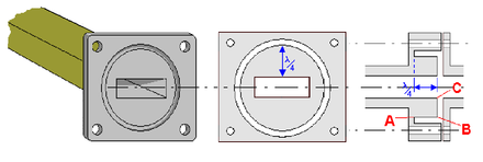
When connecting a waveguide to other devices, the electrical resistance must be very low along the entire circumference, as high currents can flow in the wall. A simple pressure contact cannot keep the contact resistance permanently low, which is why a λ / 2 transformation line AC is used in the flange , which transforms a short circuit at A into a short circuit at C (see special case λ / 2 ). A waveguide mode is selected in which there is a voltage maximum at C (see middle picture).
Since only small currents flow in the middle at point B , any contact resistance there has little effect. At this point you can even install an insulating rubber plate in order to fill the waveguide with protective gas. This principle of the resonance seal is also used to seal the door of a microwave oven with high frequency technology.
A waveguide can be terminated without reflections by means of a wave sump .
history
The first ideas for waveguides and coaxial cables go back to Joseph John Thomson and Oliver Lodge in 1893 and 1894. The first mathematical elaboration of the processes comes from Lord Rayleigh , who suggested around 1897 to remove the inner conductor of the coaxial cables already known at the time so that the electromagnetic wave, guided only through the outer wall, could propagate therein. He described the processes through reflections of the wave on the sheathing, similar to what is the case with fiber optic cables . Rayleigh was also the first to realize that every waveguide must have a lower limit frequency, which is determined by its dimensions. The first practically used waveguides, initially with a circular cross-section, were built in 1932 by George Clark Southworth and J. F. Hargreaves. Waveguides became more widespread with the emergence of military radar technology in World War II . Civil applications, such as communications satellites , followed in the decades that followed.
Waveguide frequency bands
A waveguide with certain dimensions is only sensibly used in a certain frequency range with less than one octave bandwidth . No propagation is possible below the lower limit frequency and the electromagnetic wave is blindly attenuated; above the upper frequency limit , in addition to the desired fundamental mode, undesired higher modes are capable of propagation. Commercially available rectangular waveguides are available for the following frequency ranges, among others:

| Frequency range (in GHz ) |
Band name |
designation | Width (in mm ) |
Width (in inches ) |
|
|---|---|---|---|---|---|
| DIN 47302 / IEC 153 | EIA | ||||
| 0.77 ... 1.14 | UHF / L | R 9 | WR 975 | 247.65 | 9,750 |
| 1.12 ... 1.7 | L. | R 14 | WR 650 | 165.10 | 6,500 |
| 1.7 ... 2.6 | LA | R 22 | WR 430 | 109.22 | 4,300 |
| 2.2 ... 3.3 | LS | R 26 | WR 340 | 86.36 | 3,400 |
| 2.6 ... 3.95 | S. | R 32 | WR 284 | 72.14 | 2.840 |
| 3.22 ... 4.90 | A. | R 40 | WR 229 | 58.17 | 2.290 |
| 3.95 ... 5.85 | G | R 48 | WR 187 | 47.55 | 1,872 |
| 4.64 ... 7.05 | C. | R 58 | WR 159 | 40.39 | 1,590 |
| 5.85 ... 8.2 | J | R 70 | WR 137 | 34.85 | 1.372 |
| 7.05 ... 10.0 | H | R 84 | WR 112 | 28.50 | 1.122 |
| 8.2 ... 12.4 | X | R 100 | WR 90 | 22.86 | 0.900 |
| 10.0 ... 15.0 | M. | R 120 | WR 75 | 19.05 | 0.750 |
| 12.4 ... 18.0 | P | R 140 | WR 62 | 15.80 | 0.622 |
| 15.0 ... 22.0 | N | R 180 | WR 51 | 12.95 | 0.510 |
| 18.0 ... 26.5 | K | R 220 | WR 42 | 10.67 | 0.420 |
| 21.7 ... 33.0 | R 260 | WR 34 | 8.64 | 0.340 | |
| 26.5 ... 40.0 | R. | R 320 | WR 28 | 7.11 | 0.280 |
| 33.0 ... 50.0 | Q | R 400 | WR 22 | 5.69 | 0.224 |
| 40.0 ... 60.0 | U | R 500 | WR 19 | 4.78 | 0.188 |
| 50.0 ... 75.0 | V | R 620 | WR 15 | 3.76 | 0.148 |
| 75.0 ... 110 | W. | R 900 | WR 10 | 2.54 | 0.100 |
| 90 ... 140 | R 1200 | WR 8 | 2.032 | 0.080 | |
| 110 ... 170 | WR 6 | 1.651 | 0.065 | ||
| 140 ... 220 | WR 5 | 1.295 | 0.051 | ||
| 170 ... 260 | WR 4 | 1,092 | 0.043 | ||
| 220… 325 | WR 3 | 0.864 | 0.034 | ||
This table is based on a width-to-height ratio of 2: 1. The lower recommended transmission frequencies are on average 1.26 times higher than the critical lower limit frequencies resulting from the width, the upper transmission frequencies are on average 1.48 times the lower recommended transmission frequencies. The factor 1.86 (mean value) of the upper transmission frequencies for the respective critical lower limit frequency ensures monomode propagation (value <2).
For the WRxxx designation of the waveguide: The width of the waveguide is expressed in% of an inch (1 inch = 25.4 mm). A WR-28 waveguide is thus 28% of an inch = 7.11 mm wide.
Waveguides in practice

Waveguides are used:
- in the microwave oven (there is only a short distance between the magnetron and the oven)
- on directional radio systems and radio telescopes for antenna feed (see also horn radiators )
- in satellites for antenna feed and to feed the receiving amplifier
- in the plasma generator as a connection between the magnetrons and the plasma chamber
- in radar devices for transmitting the high transmit pulse power to the antenna and the received echo back to the receiver
- in particle accelerators to feed the cavity resonators .
A line fan keeps moisture out of the environment, which could distort the adaptation of the waveguide.
literature
- Horst Stöcker: Pocket book of physics. 4th edition. Verlag Harry Deutsch, Frankfurt am Main 2000, ISBN 3-8171-1628-4
- Communication technology, part 3 Wire-based communication - line technology. Institute for the Development of Modern Teaching Methods e. V., Bremen
- Werner Bächtold: Linear elements of high frequency technology. 2nd revised edition, Hochschulverlag AG at ETH Zurich, Zurich 1998, ISBN 3-7281-2611-X
- Wilfried Plaßmann, Detlef Schulz (Hrsg.): Handbook of electrical engineering. 5th edition, Vieweg & Teubner Verlag, Wiesbaden 2009, ISBN 978-3-8348-0470-9 .
- Hans Fricke, Kurt Lamberts, Ernst Patzelt: Basics of electrical communication. BG Teubner Verlag, Stuttgart 1979.
- Hans Heinrich Meinke, Friedrich-Wilhelm Gundlach: Pocket book of high frequency technology. 5th revised edition. Vol. II. Springer Verlag, Berlin 1992, ISBN 3-540-54715-0 .
- Klaus W. Kark: Antennas and radiation fields. 6th edition, Springer Fachmedien, Wiesbaden 2017, ISBN 978-3-658-13964-3 .
Web links
- Quasi-optical derivation of the fields of the waveguide waves (accessed on July 14, 2017)
- Overview of waveguides (accessed on July 14, 2017)
- High frequency technology I waveguide (accessed on July 14, 2017)
- Modes in wave propagation (accessed on July 14, 2017)
Individual evidence
- ↑ TK Sarkar, Robert Mailloux, Arthur A. Oliner, M. Salazar-Palma, Dipak L. Sengupta: History of Wireless . John Wiley & Sons, 2006, ISBN 0-471-78301-3 , pp. 90 and 129 .


![\ lambda _ {H, nm} = {\ frac {\ lambda _ {0}} {\ sqrt {1- \ lambda _ {0} ^ {2} \ left [\ left ({\ frac {n} {2a }} \ right) ^ {2} + \ left ({\ frac {m} {2b}} \ right) ^ {2} \ right]}}}](https://wikimedia.org/api/rest_v1/media/math/render/svg/f77d33c1d4dc6eaa6250d62f066571c5c1958ecd)


