
optical fiber


Fiber optic cables (LWL) or fiber optic cables (LLK) are cables and lines for the transmission of light that consist of fiber optics and are partially assembled with connectors . The light is guided in fibers made of quartz glass or plastic ( polymer optical fibers ). They are often also referred to as fiber optic cables , with several optical waveguides typically bundled in these, which are also mechanically reinforced to protect and stabilize the individual fibers.
From a physical point of view, optical waveguides are dielectric waveguides . They are made up of concentric layers; in the center is the light-guiding core , which is surrounded by a cladding with a slightly lower refractive index and additional protective layers made of plastic. Depending on the application, the core has a diameter of a few micrometers to over a millimeter . A distinction is made between fiber optics according to the course of the refractive index between core and cladding ( step index or gradient index fibers ) and the number of vibration modes that can propagate , which is limited by the core diameter.
Multimode fibers , in which several thousand modes can propagate, have a strongly structured beam profile (see picture on the right). In single - mode fibers that have a very small core diameter, only the so-called basic mode can propagate, the intensity of which is approximately normally distributed in the radial direction . The number of modes that occur influences the signal transmission, as each mode takes a different length of light path. Therefore, with increasing length, multimode fibers show greater signal falsification ( mode dispersion ) than single-mode fibers, which are therefore more suitable for signal transmission over long distances.
Fiber optic cables are primarily used in communications engineering as a transmission medium for wired communication systems in fiber optic networks and have replaced electrical transmission on copper cables in many areas because they achieve greater ranges and transmission rates . Optical fibers are also used in a variety of ways in other areas, such as
- for the transmission of energy as a fiber optic cable for the flexible transport of laser radiation for material processing and in medicine
- For lighting and imaging purposes, inter alia, in microscope lighting , fiber optic cables and image guides in endoscopes, and for lighting equipment and buildings and for decorative purposes
- in measurement technology as a component of fiber optic sensors , on spectrometers and other optical measuring devices .
history
As early as 1870, John Tyndall tried to direct light through a jet of water. In the years that followed, scientists and technicians around the world were concerned with the possibilities of transmitting light signals through various media. In the mid-1950s, optical conductors were mainly used to illuminate internal organs in medical technology ; the loss of light in the optical conductor was still too great for other applications. Only with the development of the first laser by Theodore Maiman in 1960 was it possible to transport light through a medium in a concentrated manner. The targeted transmission of information via fiber optics now moved from the experimental phase to the technical implementation.
The first optoelectronic fiber optic system was invented by Manfred Börner in 1965 . He designed a long-range optical transmission system that combined laser diodes , glass fibers and photodiodes . In 1966 he applied for a patent for the system for the company AEG - Telefunken . All optical long-distance transmission systems still work today according to this system principle proposed by Manfred Börner. For his invention, Börner was awarded the Eduard Rhein Prize in 1990.
In 1966, Charles Kuen Kao and George Hockham discovered that it is primarily impurities in the glass that lead to losses during transmission. Kao was honored with the Nobel Prize in Physics in 2009 for his pioneering work in the field of fiber optics . In 1970, the American company Corning Inc. produced and developed the first fiber-optic cable that was able to transmit signals over long distances without major losses. From now on, the use of fiber optic cables for the transmission of telephone signals was steadily promoted, and as early as 1978 the Deutsche Bundespost connected the exchanges in Aßmannshauser Strasse and Uhlandstrasse in Berlin-Wilmersdorf over a 4 km long connecting route made of several glass fibers. In the years that followed, fiber-optic cables were continuously improved, and ever greater amounts of data could be transmitted over ever longer distances at ever higher data rates. In 1985, for example, British Telecom first transmitted signals without intermediate amplification over a distance of 250 km.
In 1987 Heraeus developed a process for the production of high-purity, synthetic quartz glass from the gas phase. Using synthetic quartz glass, metallic contamination and traces of moisture in natural quartz glass could be reduced by several orders of magnitude. The quartz glass preforms produced by Heraeus make up around 95 percent of the glass fibers for optical communication.
In the beginning, fiber optic cables had too much attenuation compared to electrical coaxial cables , which ruled out their use for longer distances. This has been reversed over the years. Today, fiber-optic cables span our planet and form the backbone of global communication and information transfer. AT&T , NEC and Corning set a new world record in May 2009. On a single fiber optic they transmitted over a distance of 580 km on 320 channels with a single data transmission rate of 114 gigabits per second and thus achieved a total data transmission rate of 32 terabits per second.
construction

1 - the core (engl. Core )
2 - shell (engl. Cladding ) with n K > n M
3 - protective coating (engl. Coating and / or buffer ) and
4 - outer shell (engl. Jacket ). For the proportions of the individual areas, see the table in the text.

The glass fibers, known as optical waveguides, consist of a core ( 1 - English core ) and a surrounding cladding ( 2 - cladding ) with a slightly lower refractive index ( n core > n cladding ). The resultant total reflection at the boundary layer to the core causes the radiation to be guided. The cladding usually consists of pure quartz glass (SiO 2 ) and the higher refractive index in the core is achieved by doping with germanium or phosphorus , which means that the amorphous silicon dioxide structure of the quartz glass also contains small amounts of germanium dioxide (GeO 2 ) or phosphorus pentoxide (P 2 O 5 ) arise. However, it is also possible to produce the core from pure SiO 2 and to dop the cladding with boron or fluorine , which leads to a reduction in the refractive index. (Pure SiO 2 cores are better suited for the transmission of wavelengths in the blue and ultraviolet spectral range.)
The jacket also has a protective coating ( 3 - English coating and / or buffer ) and an outer protective cover ( 4 - English jacket ). The jacket coating is a protection against mechanical damage and usually consists of a coating made of special plastic (such as polyimide , acrylic or silicone ), which also protects the fiber from moisture. Without the coating, the microcracks on the fiber surface would lead to a considerable reduction in the mechanical strength.
Patch cables (mostly simplex or duplex ) and multi-core underground cables can be designed as fiber optic cables. In patch cables, the individual glass fibers are protected by a plastic or metal jacket a few millimeters thick , and underground cables are additionally provided with metal wires or cables for mechanical stabilization on the inside, and possibly with a metal braid on the outside to protect against damage from the outside (such as animal bite).
The core of polymer optical fibers (POF) usually consists of polymethyl methacrylate (PMMA) and less often of polycarbonate (PC). The cladding of these fibers is lightly doped with fluorine in order to obtain a lower refractive index. Coating can be dispensed with with POF, as the material used is less sensitive to mechanical stress than quartz glass. There are also fibers with a quartz glass core and a sheath made of fluorine-doped plastic, which are referred to as hard-clad silica fibers (HCS) or polymer-clad silica fibers (PCS). To improve the mechanical and thermal properties, they can also be provided with a coating (sometimes made of ethylene-tetrafluoroethylene - ETFE).
How it works and types


Optical waveguides are dielectric waveguides for the transmission of electromagnetic radiation from the UV (approx. 350 nm) to the IR spectral range (approx. 2500 nm). Depending on the geometry and condition, only certain vibration modes can propagate in them , which differ from one another in the spatial distribution of the electric and magnetic field strength . In metallic waveguides, the modes are transversal-electrical (TE) and transversal-magnetic (TM), that is, their electrical or magnetic field strength is aligned purely transversely to the direction of propagation, the corresponding longitudinal field component disappears (TE modes = E y , H x , H z [ E z = 0] or TM modes = H y , E x , E z [ H z = 0]). In contrast to metallic waveguides, the TE and TM modes in optical waveguides generally do not occur separately from one another, and as a result of the rotationally symmetrical refractive index profile, so-called hybrid modes exist in which both field components are always present in the direction of propagation. These are referred to as HE ( E y , H x , H z ) or EH modes ( H y , E x , E z ) according to the main field components present .

The indices characterize the structure of the intensity distribution: m zeros in the radial direction (vertical row of images), 2 · l zeros with 360 ° rotation of the angular coordinate ( l pairs of nodes; horizontal row of images). Black are areas of negative field strength; the intensity (brightness) proportional to the square of the field strength is just as great there as in the white areas. Only at the transitions does the intensity go to zero (zero point of the field strength).
In the case of optical waveguides, the difference in the refractive index between the core and the cladding is generally very small (Δ ≈ 0.003); one speaks of a weakly guiding waveguide . For this special case, the transverse field components are approximately linearly polarized and the field components in the direction of propagation are negligible. The modes approximated in this way are called linearly polarized (LP). When designating the LP l, m modes, the indices characterize the structure of the intensity distribution: m zeros in the radial direction, 2 · l zeros with a 360 ° rotation of the angular coordinate ( l node pairs). The modes arise from the hybrid modes and are partly linear combinations of individual HE / EH modes. (In the hybrid modes, the indices denote the structure in the X and Y directions, for example the LP 01 mode is derived from the HE 11 mode).
Depending on the core diameter and the difference in refractive index, either only the fundamental mode or several higher modes can propagate in an optical waveguide. The division is made into single-mode fibers ( SMF), in which only the LP 01 basic mode can propagate for certain wavelength ranges , and multimode fibers ( multi-mode fiber , MMF), which are usually more than a hundred to several thousand modes.
With regard to the fiber structure, further distinctions are made within the two types of fiber:
- In the case of multimode fibers, a distinction is made between step index fibers and gradient index fibers , with the refractive index changing radially outwards between the core and the cladding glass in the form of a step, with the latter changing continuously in the form of a parabola .
- Single-mode fibers are typically only available as step index fibers, but certain properties can be manipulated in a targeted manner by introducing special structures or doping profiles. For example in polarization-maintaining , dispersion-compensating or bend-insensitive single-mode fibers.
Multimode fiber


The core diameter of multimode fibers is 50 µm to over 1500 µm. The most frequently used multimode glass fibers in the telecommunications sector are 50 µm and 62.5 µm graded index fibers ( see: Fiber categories and areas of application ). The core of these fibers is surrounded by a cladding with 125 µm and a coating with an outer diameter of 250 µm (typical values for core diameters up to almost 100 µm). Larger core diameters are provided with a jacket of 15 to 30 µm and a coating of 50 µm thickness ( see: table ).
Step index fiber
In multimode fibers, the guidance of the light can be described optically by the total reflection occurring at the boundary layer between core and cladding. For the simple case of a step-index fiber is apparent from the Snell's law of refraction with different refractive indices for the core (Engl. Core , ) and the jacket (Engl. Cladding , ) a maximum angle (to the perpendicular to the boundary layer, see picture below) for total reflection from to:


This in turn results in a maximum acceptance angle to the optical axis of the fiber (with the refractive index of the surrounding medium, usually air with ):


The product of the refractive index of the surrounding medium and the argument of the inverse sine (arcsin) is referred to as numerical aperture referred to the fiber, and results for to:


The numerical aperture depends on the difference in the refractive index between the core and cladding and is around 0.2 to 0.3 for multimode fibers and around 0.1 for single-mode fibers. The maximum acceptance angle at which coupled light can still be guided in the fiber results in an acceptance cone , which, due to the reversibility of the light path, also corresponds to the exit cone .

Due to the size of multimode fibers (core diameter is much larger than the wavelength), as mentioned above, several modes can propagate. The typically more than one hundred to several thousand modes can be viewed as a multitude of interfering light paths and generate a highly structured beam profile at the fiber output ( see picture ). This in turn is heavily dependent on the type of light coupling (illumination of the fiber depending on the light source used, see also: Over-Filled or Reduced-Mode-Launch ) and the bending of the fiber ( mode mixing ). Due to the different lengths of the light paths, there are runtime differences that cannot be neglected when transmitting messages over large distances, which have a negative effect on the signal quality and bandwidth ( mode dispersion ).
Gradient Index Fiber
In order to reduce the transit time differences in step index fibers, so-called gradient index fibers (also gradient fibers) are used, in which the refractive index gradually decreases from the fiber core towards the outside, i.e. has a gradient . While with the step index fiber the (group) transit time differences of the modes in the simple geometrical-optical image correspond more or less to the geometrical path differences (long path results in a long flight time), the relationships with the gradient index fiber are significantly more complex. Here the transit time per unit of travel is shorter in the outer areas because of the lower refractive index. In the case of a parabolically falling refractive index ( exponent = 2), for example , meridional rays, that is rays through the fiber axis, run roughly along a sinusoidal path. These rays travel a longer distance than rays along the fiber axis, but due to the outwardly decreasing refractive index they catch up again in the outer area. With a suitable profile formation, the alignment of all rays or all modes capable of propagation can be up to three orders of magnitude better than with a step index fiber.
In order to correctly dimension such graded index fibers with an optimal refractive index profile, it must be taken into account that the refractive index does not only depend on the location, but also on the wavelength at the same time. Since the profile is realized in the radial direction by doping the substance, the substance changes and thus also the material dispersion . The refractive index is therefore dependent in a complex way on the variables of location and wavelength. The higher the bandwidth of a gradient index fiber, the better the transit times of the beams or modes have to be matched to one another. The calculation of the wave propagation and the transit time differences in gradient index fibers is very complex and can be carried out using the WKB method . The optimal exponent is then only in the vicinity of two and, depending on the doping material used to set the gradient profile, there is usually an exponent that differs significantly from two. An adjustment of the time-of-flight differences by up to three orders of magnitude compared to the step index fiber can only be achieved through a highly precise implementation of the optimal exponent. Due to the influence of the material dispersion (wavelength dependence of the refractive index), it must also be noted that the optimal profile, and thus the maximum bandwidth of the fiber, also depends on the operating wavelength of the light source used.
Single mode fiber
If the core diameter is only a few multiples of the wavelength of the light, higher transverse modes are not supported. However, light can be transmitted in the LP 01 basic mode. Fibers that are designed for this operation are single-mode fiber , single-mode fiber (engl. Single-mode fiber , SMF) or single-mode fiber called. The mode structure of single-mode fibers, i.e. the transversal dependence of the electric and magnetic field , can only be determined by using Maxwell's equations and the resulting wave equation . With this wave-optical approach, the solution obtained is the parameter normalized frequency or V-number , which for the case of a step index fiber is derived as follows from the numerical aperture (or the refractive indices of the core and cladding) and the core diameter of the fiber, as well as the used Wavelength gives:


The corresponding fiber is single-mode only for values of V <2.405 and only the LP 01 basic mode can propagate. With larger values, higher transverse modes occur and the so-called cut-off wavelength can be specified for each fiber , up to which single-mode operation still prevails ( ):


Single-mode fibers usually have a core diameter of 3 to 9 µm, the outer diameter with the cladding (refractive index lower by about 0.003) being 125 µm here too. The transmission of the power takes place mainly in the core of the fiber. The approximately Gaussian intensity distribution of the LP 01 basic mode extends into the cladding and there is thus an exponentially rapidly decaying evanescent field in the inner area . Therefore, the mode field diameter (engl. Is used for single mode fiber mode-field diameter MFD) is indicated, and the amplitude of the fashion in their radial course to 1 / e, or at the fiber output, the intensity ( irradiance ) in the near field at 1 / e 2 dropped is. By approximating the field distribution of the fundamental mode by a Gaussian distribution , the following relationship between core and mode field diameter (see graphic on the right), also known as Markuse's formula, is obtained for a step index fiber:

The graphical representation of the equation shows that in the single mode range for V <2.405 the mode field diameter is always larger than the core diameter. Furthermore, the mode field diameter increases for longer wavelengths, since the normalized frequency V decreases with higher wavelengths (see equation above for V ). As a result, single-mode fibers can only be used in a range up to approx. 200 to 300 nm above the cut-off wavelength , since the basic mode that is capable of propagation is increasingly poorly guided at higher wavelengths and the bending losses due to the increased proportion of in the intensity distribution extending across the mantle increase.

For example, the core diameter of the Corning SMF-28e single mode fiber is 8.2 µm, while the MFD is 9.2 µm at 1310 nm or 10.4 µm at 1550 nm Fiber can be measured, calculated or roughly measured in the near field. However, the measurement of the far field with subsequent reverse transformation using the Hankel transformation is more precise . At Corning , for example, the Variable Aperture Method in the Far Field (VAMFF) according to TIA / EIA standard FOTP-191 is used as a reference method .
Comparison between single mode and multimode fibers
The following table shows the proportions of core, sheath and coating for some common monomode and multimode fibers. For single mode fibers, the mode field diameter is usually specified instead of the core diameter. Furthermore, the corresponding cut-off wavelengths are given for the single-mode fibers, below which higher modes also exist. Typically, the single mode fibers are suitable for wavelengths up to 200-300 nm above the cut-off wavelength. With increasing wavelengths, the proportion of the power transported in the fiber cladding increases ( MFD ~ λ) and the corresponding fiber becomes more sensitive to bending and the coupling efficiency decreases. (The fiber types shown in italics are not pure glass fibers, see POF and PCS .)
| designation | Manufacturer | Fiber type | Diameter (in µm) | ||
|---|---|---|---|---|---|
| Core or MFD | coat | Coating | |||
| 405-HP | Nufern | Single mode (λ cutoff < 400 nm) | 3.5 (515 nm) | 125 | 245 |
| 630-HP | Singlemode (λ cutoff < 600 nm) | 4.0 (630 nm) | |||
| 1060-XP | Singlemode (λ cutoff < 920 nm) | 6.2 (1060 nm) | |||
| SMF-28e | Corning | Singlemode (λ cutoff <1260 nm) | 10.4 (1550 nm) | ||
| InfiniCore 600 | Multimode (gradient index) | 50 | |||
| InfiniCore 300 | Multimode (gradient index) | 62.5 | |||
| MM-S105 | Nufern | Multimode (step index) | 105 | ||
| K200 / 230 | Leoni | Multimode PCS (step index) | 200 | 230 | 500 |
| AS-400/440 IR | Vacom | Multimode (step index) | 400 | 440 | 480 |
| Optran UV 600 | CeramOptec | Multimode (step index) | 600 | 660 | 760 |
| GK-40 | Mitsubishi | Multimode POF (step index) | 980 | 1000 | |
| Optran HUV 1500 | CeramOptec | Multimode PCS (step index) | 1500 | 1550 | |
Limits of transmission
Both the length of the transmission path and the transmission rate are limited by the properties of the fiber optic cable. The maximum transmission distance is reached with digital signals when the receiver can no longer reliably recognize the edges of the signal. This is the case when the signal is too weak or when the waveform is too distorted. The lower the losses per kilometer, the further a signal can be transmitted before it becomes too weak. The dispersion influences how much wave trains are deformed during transmission. The spectrum of a signal is wider, the higher its clock rate. For a given dispersion, the deformations therefore increase with the cycle rate.
Losses due to fundamental material properties

The intrinsic losses occurring during the light transmission in glass fibers are due to fundamental material properties and undesired contamination of the glass used .
There are material-specific absorption bands in the ultraviolet and infrared spectral range. The foothills each extend into the area between the optical data transmission (near infrared, NIR), and would result in a theoretical attenuation minimum of around 1500 nm if the additional loss mechanisms described below were neglected.
- The UV absorption is based on electronic transitions in the complex band structure of the glass, which is given by the varying bond lengths and bond angles in the irregular silicon dioxide structure (SiO 2 ). The band transitions are caused by the excitation of phonons and excitons and their possible interaction with one another. The UV absorption of amorphous materials such as glass shows a typical exponential decay with increasing wavelength, which as Urbach-streamer (engl. Urbach tail ) are referred to.
- In the infrared spectral range, material resonances lead to absorption bands that are mainly due to molecular vibrations of the Si-O, Ge-O and PO bonds.
The UV absorption is also superimposed by the Rayleigh scattering , which is caused by the statistical amorphous structure of the glass and decreases with 1 / λ 4 towards longer wavelengths. It predominates in the near infrared spectral range up to approx. 1500 nm and makes a more decisive contribution to the overall attenuation than the outgrowths of UV absorption. The Brillouin and Raman scattering , which also occurs in glass fibers, can typically be neglected in most applications, since their contribution to attenuation is very small. Possible influences by non-linear effects in these scattering processes only occur when high optical powers are used ( stimulated Brillouin or Raman scattering).
Other causes are contamination of the fiber material, mainly water absorbed during the manufacturing process, or of the raw material. Higher harmonics of the molecular vibrations of the OH bonds (fundamentals around 2800 nm) generate additional absorption maxima at 950 nm, 1240 nm and 1380 nm, water bands which are also referred to as water peaks . The individual contributions to the energy loss result in a wavelength-dependent total loss, as shown in the figure on the right. Simple fibers are therefore operated in the spectral ranges around the minima around 850 nm, 1310 nm ( O-band ) or 1550 nm ( C-band ).
A further development of the standard single-mode fiber (SSMF) are the so-called low water peak fibers (ITU-T G.652.C and G.652.D) and zero water peak fibers. In contrast to SSMF, these fibers are made (almost) anhydrous through improved manufacturing processes and raw materials, which means that attenuation in the wavelength range between 1260 nm and 1625 nm can be greatly reduced. With these fibers, the so-called E-band ( extended band ) is opened for data transmission. This area is mainly developed with CWDM technology ( coarse wavelength division multiplex , dt. 'Coarse wavelength division multiplexing '), which makes it possible to use very inexpensive, uncooled lasers for transmission due to the large channel spacing .
Bending losses

With bending radii of the glass fibers of a few centimeters, losses arise due to the radiation of power from the core into the cladding. For multimode fibers, this can be explained in terms of ray- optics by the fact that the limit angle for total reflection is not reached at the bent point and part of the light escapes from the glass fiber core. For single- mode fibers, the wave-optical approach applies , which states that part of the transported power always extends to the jacket. The mode field diameter is always larger than the core diameter and increases with the wavelength. In the outer area of the bending point, with increasing distance from the core, the path is lengthened, which causes the phase fronts to remain, since the maximum propagation speed in the cladding cannot be exceeded. The wavefront is no longer flat , resulting in a radial component of the Poynting vector , which results in energy being radiated. The effects described become noticeable in the form of an increase in attenuation which, depending on the power budget, route length and bend, can lead to total failure of the transmission.
Especially for the area of fiber to the home (FTTH) and the associated poor installation conditions in residential buildings, the glass fiber manufacturers have recently developed new glass fibers with reduced bending loss . With these low-bending-loss single-mode and multimode fibers, the aim is to reduce the refractive index in the cladding through suitable measures or to modify it so that the mode field diameter is reduced and thus less power is radiated into the cladding. Proposed methods are the introduction of a ring-shaped fluoride- doped layer in the cladding, in which the refractive index is reduced in the form of a trench around the core ( trench-assisted ), the introduction of a ring-shaped nano- or microstructure ( photonic crystal structure ) from cavities in cladding ( photonic-crystal fiber , PCF for short ), which also leads to a reduction in the effective refractive index (see waveguide dispersion ) in the corresponding areas.
Such fibers, which are less sensitive to bending, make it possible to ensure almost lossless transmission even with bending radii in the range of less than 10 mm. In the singlemode area they are specified according to ITU-T G.657, categories A and B, with category A meeting the requirements for standard single-mode fibers according to ITU-T G.652.
Insertion and coupling losses
When coupling the light into the fiber, as well as when connecting fibers by means of plug and splice connections , insertion or coupling losses can occur due to several factors:
- Core eccentricities and different mode field diameters of the fibers to be connected
- longitudinal and transversal misalignment and angular misalignment of the fiber ends
- Surface reflections at the fiber ends
- Incorrect adjustment of the numerical aperture and focus size between the coupling optics and the fiber.
When connecting fiber optic cables, it is important that the position of the fiber core is centered (core eccentricity) and that the dimensions and roundness of the fibers are precisely maintained and are compatible with one another. The eccentricity of the fiber core (offset between the center of the fiber core and the center of the fiber cladding) is less than 0.5 µm in today's single-mode fibers. Further transversal offsets can arise from tolerances during connector assembly , where the fiber is glued into a ferrule with a bore of, for example, µm ( single-mode fibers) or µm (multimode fibers), as well as tolerances in the guide sleeves of the connector receptacles, which range from 1 to 2 µm. Since the signal in single-mode fibers is transported through a core a few micrometers thick, any mismatch leads to a partial overlap and thus to a loss of performance.


The larger core diameter of multimode fibers allows greater tolerances at the transition between two fibers. However, applications such as 10 Gigabit Ethernet and especially 40 and 100 Gigabit Ethernet have only small reserves for attenuation and losses, and excessively high tolerances and deviations can therefore quickly reach their limits here too.
Dispersion
Various dispersion effects contribute to the deformation of the signal shape modulated onto the light during transmission, which is due to different propagation speeds of different signal components: The light used to transmit information has a spectral width that is at least as large as the bandwidth of the modulated signal Useful signal. If different wavelengths now reach the receiver with different delays, the signal shape of a square, for example, blends. The deformation is greater, the longer the fiber stretch and the greater its dispersion at the wavelengths used.
- Mode dispersion : In step-index multimode fibers, different modes can propagate at different speeds . This depends on the radial course of the refractive index. A parabolic outwardly lowering refractive index lowers the mode dispersion in the ideal case to zero. This type of dispersion is not required for single-mode fibers; it dominates the
-
Chromatic dispersion : It is the different speed of propagation depending on the wavelength. A practical unit of measurement of chromatic dispersion for the transmission of digital signals is picoseconds per kilometer of fiber length and nanometer of wavelength difference, ps / (km · nm). Chromatic dispersion is the sum of two mechanisms:
- Material dispersion: Unlike in a vacuum, the speed of propagation of light in glass depends on the frequency of the light, which can also be observed in glass lenses as a chromatic error ( chromatic aberration ). The material dispersion changes its sign depending on the type of glass in the near infrared. This means that at a certain wavelength the material dispersion disappears or that materials can be selected for which the material dispersion is zero at the desired wavelength.
- Waveguide dispersion : The effective refractive index is between that of the fiber core and the lower index of the cladding. The weighting itself depends on the wavelength: the longer the wave, the deeper the mode penetrates the cladding and the lower the effective refractive index and thus the higher the speed of propagation. The choice of cladding material thus influences the dispersion of the optical waveguide - the smaller the difference in refractive index, the lower the waveguide dispersion. But the numerical aperture also decreases.
- Polarization mode dispersion (PMD): Light propagates atdifferent speeds in a birefringent medium depending on the polarization. A glass fiber is either birefringent due to its shape or due to external influences such as bending or temperature fluctuations. The PMD can besuppressed by polarization-maintaining optical fibers (PMF), in which case the light source may only excite one polarization mode. However, due to the higher attenuation and higher manufacturing costs, this type of fiber is only used on short transmission routes and in measurement technology. Such fibers are deliberately inhomogeneous radially, e.g. B. by a geometric asymmetry of the core or by stress elements in the fiber cladding, which lead to stress birefringence in the symmetrical core.
Nowadays, non-zero dispersion fibers (ITU-T G.655.C) are used as singlemode fibers for wide area networks . They combine very low attenuation with low dispersion in the C-band ( conventional band ), which, in contrast to standard single-mode fibers (SSMF), enables transmissions over longer distances without external dispersion compensation.
The refractive index of glass depends not only on the frequency but also on the amplitude of the light transmitted through it. For certain signal forms called soliton , its influence cancels out the deformations caused by the frequency-dependent dispersion. For more than three decades it has been pointed out that it is in principle possible to operate a fiber link over thousands of kilometers without a repeater . However, signal amplification is necessary. However, practical hurdles have so far prevented widespread use in fiber communication.
Manufacture of glass fibers
The production of glass fibers takes place in two steps. First, a so-called will preform by chemical vapor deposition ( English chemical vapor deposition , CVD) generated, it is at around a glass rod of typically 1 m in length and 10 to 50 mm diameter. The preform already has the refractive index profile of the later fiber, which is later drawn from this by melting.
Manufacture of the preform
In order to achieve the lowest possible attenuation in glass fibers, a particularly high chemical purity of the quartz glass produced is required . To achieve this, various CVD processes are used, in which high-purity silicon dioxide (SiO 2 ) is deposited on the preform from the gas phase . The processes used differ mainly in whether the deposition process takes place inside or on the outside of the preform . In all processes, a chemical reaction of tetrachlorosilane (SiCl 4 ) and oxygen (O 2 ) to silicon dioxide and chlorine (Cl 2 ) is used to produce the glass :
- .

For chemical reactions in the case of the specifically introduced doping (to achieve the desired refractive index profile, see structure ), the same applies depending on the valency ( germanium ) or in slight modifications, e.g. B. Boron (B) or Phosphorus (P):
- .

Outside Vapor Deposition (OVD)

The OVD process ( outside vapor deposition ) is the oldest manufacturing method. It was developed by Corning and is still used there. In this process, the glass is applied to the outside of a solid round rod made of aluminum oxide or graphite by blowing the gaseous halides and reaction gases into a burner flame in a controlled manner and then depositing the resulting glass particles on the glass rod. An even layer is achieved by rotating and propelling the rod accordingly. Several thousand layers can be applied to achieve the desired refractive index. In a subsequent sintering process , the still porous structure is compressed and any gases and water residues that are still present are removed. The inner round rod is then removed and by further heating the hollow rod that has been created, it is shrunk (collapsed) into a preform . During the collapse, there is typically a drop in the refractive index in the middle of the later fiber core, since the heating in the interior results in outgassing of the doping material germanium (Ge), in the form of germanium (II) oxide (GeO).
Vapor (Phase) Axial Deposition (VAD)

In the VAD process ( vapor phase axial deposition ), the glass is deposited on the face of a solid rotating rod, with the refractive index profile being achieved by the variable geometric arrangement of the gas burners or nozzles. Here, too, the still porous structure is later compressed by sintering, but the round rod no longer needs to collapse, and the radial refractive index drop in the core that occurs during the OVD is avoided. With this method, an endless preform can be produced, so to speak , which enables the production of particularly long fibers.
Modified Chemical Vapor Deposition (MCVD)

In contrast to the first two processes, with the MCVD process ( modified chemical vapor deposition ), the deposition process takes place inside a glass tube, which later becomes the outer area of the jacket. The gaseous halides are blown into the glass tube in a controlled manner using a suitable mixture of reaction gas (oxygen) and inert transport gases ( argon or helium ). The pipe is heated from the outside by means of a gas burner and the glass particles are deposited in the hot zones. Rotation of the tube or the burner or suitable positioning of several burner flames ensures that the separation is rotationally symmetrical. By guiding the burners along the pipe, uniform layers are then created on the inside. Since the glass tube wall is located between the burner flames and the reaction zones, the inclusion of residual gases and water vapor is avoided with this method. Here too, a sintering process follows before the collapse. Similar to the OVD process, there is also a drop in the refractive index here, as the germanium (Ge) typically used for the core escapes in the form of germanium (II) oxide (GeO) during the collapse on the inside, which later becomes the center of the fiber core forms.
Plasma Chemical Vapor Deposition (PCVD)
When PCVD method (engl. Plasma (-assisted) chemical vapor deposition , dt., Plasma-enhanced chemical vapor deposition ') is a modification of the MCVD, wherein the gas burner by microwave generators are replaced (2.5 to 3 GHz), which generate a plasma inside the tube. This is done directly on a quartz glass core rod which is usually not doped. An additional electrical heating of the tube to about 1000 ° C prevents mechanical tension between the applied layers and the carrier glass. With this process, the glass is immediately deposited with little pores and the sintering step can be dispensed with. Another advantage is the relatively high speed and the achievable layer thickness of less than 1 µm, which allows the implementation of very precise refractive index curves.
Similar processes, which are to be regarded synonymously as PCVD processes, are the PECVD process (English plasma-enhanced CVD ), the PICVD process (English plasma impulsed CVD ) and the SPCVD process (English surface plasma CVD ). which differ largely only in the type of plasma generation and the pressure used inside the pipe.
Pulling the fiber

In fiber drawing towers , an area of the blank is heated to temperatures of around 2000 ° C. At this temperature the glass becomes so soft that it can be drawn into a fiber. The associated reduction in diameter in the ratio of around 200: 1 leads to a change in length of around 1: 40,000, 40 km of fiber are created per meter of blank. The profile of the refractive index is retained during the drawing process.
While the fiber is being drawn out, the fiber diameter is constantly checked and the advance of the fiber is regulated accordingly. The bare glass fiber is immediately provided with a coating made of plastic such as polyimide , acrylic or silicone after it has been pulled out . For this purpose, the fiber is passed through an extruder and then the plastic is hardened by UV radiation. Curing by heating is also possible, but more slowly. The fiber drawing speeds are between a few hundred and two thousand meters per minute and, together with the curing time, significantly determine the height of the fiber drawing tower. A tensile strength test is carried out before the finished fiber is wound up.
Connection techniques
Optical fibers are connected to one another or to other components with plug connections or splice connections. In communications technology , these are transmitters, receivers or amplifiers, and in measurement technology , spectroscopy or medical technology, for example, lasers, sensors or detectors.
So-called optical slip rings or rotary transmitters are used to connect rotating parts , which enable continuous data transmission (analog or digital) from stationary to rotating components, such as in computer tomographs or industrial robots .
Plug connections and plug types
The majority of plug connections are plug-plug connections. The connectors used must have the lowest possible signal attenuation ( insertion loss ) and high return loss ( reciprocal value of the degree of reflection ), as well as high reproducibility and maintenance of these parameters over several hundred connection cycles.
| abbreviation | designation | Reflectance | Return loss |
|---|---|---|---|
| Pc | Physical contact | <−30 dB | > 30 dB |
| SPC | Great physical contact | <−40 dB | > 40 dB |
| UPC | Ultra physical contact | <−50 dB | > 50 dB |
| APC | Angled Physical Contact | <−60 dB | > 60 dB |
This is achieved through the use of spring-mounted, very precise cylindrical sleeves for receiving fibers (so-called ferrules ), which are brought into direct contact in the connector receptacles, which achieves an insertion loss of 0.1-0.5 dB. The ferrules, which are mainly made of metal or ceramics , are specially ground or polished with the glued-in fiber . Today only the so-called PC plugs are used ( physical contact ), with a rounded end surface (radius approx. 10-15 mm), which make physical contact with the fiber cores when plugged in.
Increasingly higher demands on the return loss of the installed plug connections ultimately led to better and better polishing qualities of the PC plugs, including the grades SPC ( super physical contact ) and UPC ( ultra physical contact ). A further increase could then only be achieved with the so-called HRL connectors ( high return loss ) or APC connectors ( angled physical contact ) (see table for values for the return loss ). With this type of connector, the connector end face is not only convex, it is also tilted by a few degrees (standard is 8 °) to the typically right angle to the fiber axis. Due to this structure, light reflected from the plug end face is refracted from the core via the cladding glass into the air and can therefore no longer interfere with data transmission. Connectors of this type have an APC as a supplement to their designation (ST / APC, SC / APC, FC / APC, LC / APC, LSH / APC etc.). UPC and APC connector types are used especially for single-mode fibers.
The most frequently used connector types today are LC ( local connector ) and SC ( subscriber connector ). From older installations, ST ( straight tip ) and LSH are also widely used. Like the MU, LX.5 and FV-45 connectors, the LC connector is one of the so-called small form factor connectors (SFF connector). These have 1.25 mm ferrules and, thanks to their smaller design, enable a higher assembly density than older connectors, such as the SC, ST and LSH connectors with 2.5 mm ferrules. A further increase in port density can be achieved with multi-fiber connectors with MT ferrules ( mechanical transfer ), such as the MTRJ, MPO or MTP connector. MT ferrules typically contain 2 (MTRJ) to 16 (MPO / MTP) fibers per row (fiber spacing 250-750 µm) and the alignment of the multi-fiber ferrule is carried out using two high-precision guide pins attached to the side.

F-SMA plug (SMA 905)

FC / PC connector

ST connector

SC connector

E-2000 connector
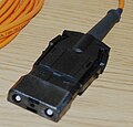
ESCON connector

MIC (FDDI) connector

LC connector

MTRJ connector

TOSLINK connector
.jpg)


Splice connections

Thermal splicing of glass fibers is a safe and low-loss connection method, but requires special equipment (splicing machine) and experience. Before splicing, the ends must be freed from the coating (with a stripping tool), trimmed flat (with a cutting tool to create high-quality fiber breaks) and positioned precisely to one another (typically done in the splicing machine). The fiber ends are then melted using a brief arc. During the melting process, the glass fiber ends are pushed together without any additional joining means. The fragile splice is then mechanically protected against moisture with a splice protector. The creation of a detachable connection, for example to enable maneuvering options between different routes within a distribution field, is done by splicing a pigtail with the installation fiber. A pigtail is a fiber optic cable that has a pre-assembled connector on one side.

Glass fiber closures contain several splice connections and connect two or more cables, each with several fibers or fiber optics . For this purpose, the fiber optic cables must be individually stripped, spliced and placed in cassettes. These are used to ensure that the remaining fibers remain unaffected in the event of a fiber disruption. A closure can accommodate over 200 individual fibers, which can take several days to install.
There are also splice connections known as ribbon or ribbon cables. With these cables, up to twelve glass fibers are housed in an adhesive matrix next to one another as a single element. The associated cables contain up to 100 such ribbons, i.e. H. up to 1200 fibers. The appropriate splicing technique always splices the entire ribbon together, i.e. H. four, six or twelve glass fibers simultaneously using an electric arc.
More techniques
In optical components there are also branches and junctions of fibers (switches). In order to pump powerful fiber lasers , several fibers of the pump laser must be connected to the active fiber. So-called fiber combiners and WDMs are used for this. So-called tapers are used to connect optical fibers with different core diameters . Furthermore, there are switches for a plurality of fibers, so-called fiber switch (engl. Fiber switch ). These can be mechanical or optical, i. H. contactless, work.
Application in communications engineering
Fiber optic cables are used in communications technology to transmit information over short and long distances with a high bandwidth . Inexpensive multimode fibers are used over short distances, and with single-mode fibers, distances from a few 10 to more than 100 km can be bridged without intermediate amplification using repeaters . Compared to copper cables, the product of bandwidth and possible distance is much higher with fiber optic cables , which means that higher data rates can be achieved or greater distances can be bridged.
In local data transmission networks ( Local Area Network and Storage Area Network ), fiber optic cables are used today with almost every network standard, such as Ethernet , Fiber Channel or InfiniBand ; Fiber Distributed Data Interface (FDDI) was also popular in the past . An extension of existing networks based on copper cables is possible with so-called media converters , which can connect network segments of different transmission media such as twisted pair cables , coaxial cables or fiber optic cables . Primarily, modular interfaces have established themselves in which the line- specific transceivers can be exchanged and which are available for various speeds, wavelengths and fiber optic connector types. There are gigabit interface converters (GBIC), small form factor pluggable (SFP or mini GBIC), XENPAK, X2, XFP, SFP +, QSFP and CFP in different generations and with different port densities Modules.
In the global area network , fiber-optic cables have been used since the late 1980s, especially for intercontinental submarine cables and transatlantic telephone cables , in order to meet the increasing demands on bandwidth and transmission rate with the rapid development of the Internet . But fiber optic cables are also increasingly used in the wide area of nationwide networks ( Wide Area Network and Metropolitan Area Network ). The fiber optic cables used are operated in the DWDM process, which enables enormous transmission capacities. Signals of different wavelengths are coupled in by means of several lasers and transmitted simultaneously on a fiber. So you have different channels on one fiber. With the help of the broadband amplifying EDFAs , a bandwidth length product of more than 10,000 (Tbit / s) · km is possible. These 4th generation systems were increasingly installed in the mid-1990s and are state of the art to this day.
At the end points of fiber optic cables, the optical signals are usually converted into electrical signals, which are then routed to individual households via coaxial cables, for example . Use is here u. a. HFC technology ( Hybrid Fiber Coax ) for cable television ( video-on-demand ). In recent years, the expansion of fiber optic networks in the access area has been driven forward, especially in Japan, the USA and Europe. The individual houses are connected directly there with fiber optics. This procedure is summarized under the term Fiber to the Basement (FTTB). In this expansion, one or two fibers are laid per building. One fiber is used for the download and the other for the upload and if only one fiber is laid, the download runs over the wavelength 1310 nm, while the upload is carried out at 1550 nm.
There are the first successful experiments in which information was transmitted in parallel via different modes. With such a space division multiplexing method , the data transmission rate could in theory be increased by a hundred or a thousand times. In practice, however, “improperly” coupling the laser pulse into a multimode fiber stimulates a large number of different modes, which mix due to the curvature of the fiber and distort the signal to be transmitted due to different transmission speeds. Thus, a higher number of stimulable modes currently still represents a certain disadvantage.
Structure of a fiber optic transmission link
Today's communication networks consist almost exclusively of fiber optic networks in their core area , whereby, as mentioned above, the direct connection of end users via fiber optic cables is being promoted. A transmission line based on optical fibers consists of the following components:
- Transmitter (conversion of electrical into optical signals)
- Transmission medium (fiber optic cable or fiber optic cable)
- Components for coupling, branching, modulation and signal regeneration (active and passive)
- Receiver (conversion of optical into electrical signals)
LEDs are used as optical transmitters at transmission rates of up to 622 Mbit / s, with a transmission power of approx. −24 to −3 dBm ( power level in dBm with a reference value of 1 mW ). Laser diodes are used for higher transmission rates (> 622 Mbit / s) , such as surface emitter diodes for transmission using multimode fibers and DFB ( Distributed Feedback Laser ) or Fabry-Pérot lasers for transmission using single-mode fibers (typical transmission powers are in the range from −10 to 13 dBm).
The optical waveguides used as the transmission medium must have the lowest possible attenuation and dispersion. Single mode fibers (low dispersion) are mainly used in the long-distance network area and multimode fibers (larger dispersion) are used in local areas or in small networks ( see fiber categories and areas of application ).
Erbium -doped fiber amplifiers (EDFA ) pumped with diode lasers are mainly used as so-called repeaters for signal regeneration and also as output and input amplifiers . As with a laser, the amplification takes place through stimulated emission , but the build-up of an optical resonator is prevented by isolators at the amplifier output . Furthermore, Raman amplifiers are used especially for DWDM applications , which, compared to an EDFA, allow simultaneous coverage of the C and L bands , and have an adjustable gain range. The amplification takes place in the actual transmission fiber. Since the gain is distributed over the entire fiber, a significantly better signal-to-noise ratio is achieved .
The optical receiver at the end of a fiber optic cable must have the greatest possible sensitivity (approx. −30 to −53 dBm) and be very broadband. Mainly pin diodes are used , but also avalanche photodiodes (APD), which are more sensitive than pin diodes due to their internal amplification.
Fiber categories and areas of application
Similar to copper technology, optical classes and categories were introduced to identify the transmission bandwidths and the performance capabilities of multimode and single-mode fibers. Due to the increasing bandwidth requirements and ever higher data rates during the transition from the Mbit to the Gbit range, as well as the introduction of (multi) Gbit protocols such as Ethernet , Fiber Channel or InfiniBand , the OM1 categories have been used since the mid-1980s , OM2, OM3, OM4 and OM5 for multimode fibers, as well as the categories OS1 and OS2 for single mode fibers. The fiber categories are specified internationally according to ISO / IEC 11801 and 24702, and the increasing number of categories included takes account of the growing requirements.
| category | Color code | Fiber type | Attenuation (dB / km) |
minimum modal bandwidth (MHz km) |
|||||
|---|---|---|---|---|---|---|---|---|---|
| EMB 1 | OFL 2 | ||||||||
| wavelength | 850 nm | 1310 nm | 1383 nm | 1550 nm | 850 nm | 850 nm | 1310 nm | ||
| Multimode fibers | |||||||||
| OM1 | orange 3 | G62.5 / 125 | 3.5 | 1.5 | n / A | n / A | n / A | 200 | 500 |
| OM2 | orange | G50 / 125 | 500 | ||||||
| OM3 | aqua | G50 / 125 | 3.0 | 1.5 | n / A | n / A | 2000 | 1500 | 500 |
| OM4 | purple 4 | 4700 | 3500 | ||||||
| OM5 | lime | G50 / 125 | 4700 | 3500 | 500 | ||||
| 953 nm | 953 nm | ||||||||
| 2470 | 1850 | ||||||||
| Monomode fibers ( single-mode fibers ) | |||||||||
| OS1 | yellow 5 | E9 / 125 | n / A | 1.0 | n / A | 1.0 | n / A | ||
| OS2 | 0.4 | 0.4 | 0.4 | ||||||
Categories for multimode fibers

Historically, there are significant differences in the methods for classifying the fiber categories for multimode fibers (OM1 – OM4). Earlier transmission methods primarily used inexpensive LEDs for transmission purposes. However, LEDs are only suitable up to a data rate of 622 Mbit / s, as their design means that they have a low focus and thus couple light both into the fiber core and into part of the cladding. One speaks here of the so-called over-filled launch (OFL). From Gbit Ethernet , surface emitters (VCSEL, vertical-cavity surface-emitting laser ) at wavelengths of 850 and 1310 nm are used, which have a very strong focus and only couple into a fraction of the fiber core. In this case, one speaks of the reduced mode launch (RML). The determination and specification of the bandwidth used to be carried out (OM1-2) with the OFL and RML method in the frequency range, which, however, proved to be insufficient for determining the transmission lengths for Gbit applications. The measurement method had to be changed, and for high-quality laser-optimized multimode fibers today (instead of the RML method), the effective modal bandwidth (EMB) in the time domain is determined using the DMD measurement method ( differential mode delay ) or the minEMBc measurement method ( English minimum effective modal bandwidth calculated ).
The fiber categories OM1 and OM2 are typically designed for LED-based applications. By reducing the core diameter to 50 µm, the mode dispersion was reduced and the bandwidth increased. The fiber categories OM3 and OM4 are only available with a 50 µm core diameter (G50 / 125) and are intended for high-speed applications such as (10/40/100) Gigabit Ethernet or Fiber Channel at 850 nm. They have an improved refractive index profile than OM1 / 2 fibers, which, due to the manufacturing process, have a slight refractive index drop in the middle of the fiber core (for example in the OVD , MCVD or PCVD process with deposition processes inside the preform), which is what makes the high bit rate RML transmission with surface emitters impaired.
| Ethernet | OM1 | OM2 | OM3 | OM4 | OS1 / OS2 | |||
|---|---|---|---|---|---|---|---|---|
| 100 Mbit / s | 100BASE-SX | 850 nm | 300 m | 300 m | 300 m | n / A | ||
| 100BASE-FX | 1310 nm | 2000 m | 2000 m | 2000 m | 2000 m | 10 km | ||
| 1 Gbit / s | 1000BASE-SX | 850 nm | 300 m | 500 m | 1000 m | 1000 m | ||
| 1000BASE-LX | 1310 nm | 550 m | 550 m | 550 m | 550 m | 5 km | ||
| 1000BASE-LX10 | 1310 nm | 550 m | 550 m | 550 m | 550 m | 10 km | ||
| 1000BASE-BX10 (single fiber ) |
1490 nm (-D) 1310 nm (-U) |
10 km | ||||||
| 1000BASE-EX | 1310 nm | 40 km | ||||||
| 1000BASE-ZX | 1550 nm | 80 km | ||||||
| 1000BASE-EZX | 1550 nm | 120 km | ||||||
| 10 Gbit / s | 10GBASE-SR | 850 nm | 30 m | 80 m | 300 m | 500 m | ||
| 10GBASE-LR | 1310 nm | 10 km | ||||||
| 10GBASE-LRM | 1310 nm | 220 m | 220 m | 220 m | 220 m | |||
| 10GBASE-ER | 1550 nm | 40 km | ||||||
| 10GBASE-ZR | 1550 nm | 80 km | ||||||
| 40 Gbit / s | 40GBASE-SR4 | 850 nm | n / A | n / A | 100 m | 125 m | ||
| 40GBASE-SR2-BiDi | 850 nm | n / A | n / A | 100 m | 150 m | |||
| 40GBASE-FR | 1550 nm 1310 nm |
2 km | ||||||
| 40GBASE-LR4 | 1310 nm | 10 km | ||||||
| 40GBASE-ER4 | 1550 nm | 40 km | ||||||
| 100 Gbit / s | 100GBASE-SR2 | 850 nm | n / A | n / A | 70 m | 100 m | ||
| 100GBASE-SR2-BiDi | 850 nm | n / A | n / A | 70 m | 100 m | |||
| 100GBASE-SR4 | 850 nm | n / A | n / A | 70 m | 100 m | |||
| Fiber Channel | OM1 | OM2 | OM3 | OM4 | OS1 / OS2 | |||
| 850 nm | 1310 nm | 1550 nm | ||||||
| 1 Gbit / s | 1GFC | 300 m | 500 m | 800 m | n / A | 10 km | 50 km | |
| 2 Gbit / s | 2GFC | 150 m | 300 m | 500 m | n / A | 10 km | 50 km | |
| 4 Gbit / s | 4GFC | 70 m | 150 m | 380 m | 400 m | 10 km | n / A | |
| 8 Gbit / s | 8GFC | 20 m | 50 m | 150 m | 190 m | 10 km | n / A | |
| 16 Gbit / s | 16GFC | 15 m | 35 m | 100 m | 125 m | 10 km | 50 km * | |
| 32 Gbit / s | 32GFC | n / A | n / A | 70 m | 100 m | 10 km | 50 km * | |
| InfiniBand | OM1 | OM2 | OM3 | OM4 | OS1 / OS2 | |||
| 850 nm | 1310 nm | |||||||
| 2 Gbit / s | 1X-SDR | 125 m | 250 m | 500 m | n / A | 10 km | ||
| 4 Gbit / s | 1X DDR | 65 m | 125 m | 200 m | n / A | 10 km | ||
| 8 Gbit / s | 1X-QDR | 33 m | 82 m | 300 m | n / A | 10 km | ||
| 8/16/24 Gbit / s | 4X / 8X / 12X-SDR ** | 75 m | 125 m | 200 m | n / A | n / A | ||
| 16/32 Gbit / s | 4X / 8X DDR ** | 50 m | 75 m | 150 m | n / A | n / A | ||
The maximum specified transmission range of the fiber category used (see table) depends on the data rate and the wavelength used (850 nm or 1300 nm). While at 10 Mbit / s to 1 Gbit / s 300 m at 850 nm are also easily possible with OM1 and OM2 fibers, the achievable length for transmission rates of more than 4 Gbit / s is limited to less than 100 m at this wavelength (Slightly different minimum transmission lengths are specified for the different high-speed applications, see table). Fibers of the OM3 and OM4 categories, on the other hand, also allow lengths of approx. 300 m at 850 nm. With OM4 fibers, the transmission length can also be increased by a few 10 meters compared to OM3 fibers for applications with more than 10 Gbit / s. OM5 was introduced in order to be able to achieve data rates of 100 to 400 Gbit / s with a few fibers using wavelength division multiplexing .
Categories for single mode fibers

In single- mode fibers , in contrast to multimode fibers, there is no mode dispersion and they allow much greater transmission distances and bandwidths. However, since single-mode fibers have a significantly smaller core than multimode fibers, which makes practical handling of light coupling and fiber connection more difficult, multimode fibers are still used for shorter distances.
The single mode fibers most commonly used in the telecommunications sector to date are intended for use in the O and C band of optical data communications around λ = 1310 nm and λ = 1550 nm. At these wavelengths lying attenuation minimum of the fiber material, and further to be in this region of erbium doped fiber amplifiers (engl. Erbium-doped fiber amplifier , EDFA ) is operated. Although the dispersion at these wavelengths is not equal to zero, its effect can be reduced by dispersion-compensating fibers. It is even advantageous that the dispersion is not equal to zero, since otherwise non-linear effects such as four-wave mixing would occur, which considerably disrupt the signal. It should be noted, however, that dispersion-compensating fibers, which are used in so-called dispersion compensation modules, can place a heavy burden on the power budget with their high attenuation.
The classes OS1 (since 1995) and OS2 (since 2006), which differ only in their maximum attenuation, are defined for single-mode fibers . Especially at 1383 nm, the so-called low-water-peak fibers of the OS2 category have low attenuation with a specified maximum value of 0.4 dB / km and are therefore suitable for the use of CWDM transmissions. The fiber category also depends on the type of installation, as it affects the attenuation values. The specification according to ITU-T G.652 cannot be clearly transferred to the OS categorization. In general, however, the OS1 category can be assigned to the fibers according to ITU-T G.652A and B, and the OS2 category to the low water peak fibers according to ITU-T G.652.C and D.
laying
They are often laid underground. The cables are housed in existing shafts, pipes or sewers and then routed to the individual buildings at the desired locations using distributors. This is inexpensive because no construction work is necessary and the respective connections can be installed quickly and easily through the input and output shafts. With FTTH ( Fiber to the Home ), the cables with a diameter of 2 mm are laid in the existing telephone connection ducts (electrical ducts).
Dark fiber
Dark fiber is a fiber optic cable that is sold or rented unconnected. The optical waveguide is between two sites point to point durchgespleißt . The buyer or renter is responsible for the transmission and transmission equipment. He also determines the use. This business model is also known as carriers carrier or wholesale business . Since this is a pure infrastructure service, this contract is not subject to the Telecommunications Act . In addition to regional power suppliers, fiber-optic cables of this type are made available in Germany by rail operators, municipal utilities, municipal associations and carrier providers such as Colt , Versatel or Telekom . In addition to the duration of the contract and the route of the line, the costs incurred mainly depend on the construction measures required for a successful connection and whether there are other interested parties / competitors for the same route. The desired bandwidth does not define the price of such a line.
Redundant fibers are included in the cables to avoid disruptions during earthworks or extensions . Unused fiber optic capacities are also referred to as dark fiber , since no light signals are transmitted when the fiber optics are not used and the fiber is therefore “dark”. If necessary, additional fibers can be put into operation thanks to the existing redundancy.
Listening methods
.jpg)
Like other transmission media, fiber optic cables are not secure against “ eavesdropping ”. There are two main points at which information from the fiber optic cable can be intercepted.
The first method starts with the splice, in which, despite the low transmission losses, good splices of less than 0.02 dB emit radiation that can be evaluated. The second method uses radiation losses at bending couplers ( coupler method). Because if a glass fiber is bent, the light flowing through largely follows the bend - however, some of the light radiates out of the fiber. Just a few percent of the light signal is enough to receive all the information transmitted. Because of the changing attenuation as a result, the process can be verified in principle. Encryption is a method to increase security against eavesdropping .
Advantages and disadvantages of fiber optics compared to copper technology
The triumphant advance of fiber optic technology is based on the decisive advantages of optical transmission over the older electrical transmission based on copper cables. The main advantages are the considerably higher possible transmission rates (gigabits to terabits per second), with at the same time very large possible ranges (up to several hundred kilometers without a repeater). This in turn requires lighter cables and less space, as well as fewer repeaters, which significantly reduces installation and maintenance costs.
Further advantages are:
- no signal interference on neighboring fibers ( crosstalk )
- no influence from electromagnetic interference fields, which u. a. the combination with high-voltage direct current transmission components makes possible
- no earthing required and galvanic separation of the connected components
- No fire initiation by lightning strike or short circuit and lower fire load, and can also be used in potentially explosive environments ( there are restrictions when using higher optical powers that escape at coupling points or in the event of fiber breakage and, in unfavorable cases, can also trigger fire or explosion. )
- high listening effort
Disadvantages are the higher assembly effort and the higher precision and care required during laying and installation, which requires expensive equipment and complex and complex measurement technology , which is why fiber to the desk is not very common.
Other disadvantages are:
- sensitive to mechanical stress and restrictions when laying, as no strong curves are possible (strongly type-dependent, e.g. for medical technology there are special types for video endoscopy )
- Power over Ethernet is not possible
Other uses
Interference-free audio connections
At the beginning of the 1990s, D / A converters and CD players were offered that communicated with an ST connection. Device examples are Parasound DAC 2000, WADIA DAC, Madrigal Proceed PDP 3 with CD transport PDT 3. However, this type of connection could not prevail against TOSLINK , a connection technology with POF , and was therefore used very rarely.
Optical connections in audio technology avoid signal interference from electrical and magnetic fields as well as from ground loops , as they create a potential separation.
Potential separation
Examples of the use of fiber optic cables for currentless signal transmission
- in power electronics and high-voltage systems, for example to transmit control signals to the thyristors at high-voltage potential . It is even possible to ignite the converter thyristors directly via the light pulses transmitted in the glass fiber (see optothyristor ).
- for the transmission of measurement signals in high-voltage systems or in a disruptive environment
- in audio systems (see above )
- for the galvanically separated network connection of medical devices (e.g. digital X-ray machines) to local networks.
measuring technology
The transmission or simultaneous acquisition of measurement signals using fiber optics makes it possible to measure a large number of physical quantities such as pressure or temperature in difficult-to-access places such as in dams or under extreme conditions such as in steelworks . Also spectrometers often have fiber optic connections. Furthermore, miniaturized glass fiber spectrometers can be produced, since the optical grating can be illuminated directly with the light exit cone of a glass fiber , and additional imaging optics can therefore be dispensed with.
With fiber optic sensors , the measured variable is not represented or transmitted by an electrical variable, but by an optical one. This makes the transmission insusceptible to external influences such as electromagnetic fields and also allows use in potentially explosive environments. There are two classes of fiber optic sensors: intrinsic and extrinsic fiber optic sensors. In the case of intrinsic fiber optic sensors, the glass fiber serves directly as a measuring sensor, that is, the optical signals are directly influenced by external parameters, for example bending losses. The fiber optic cables are both a sensor and a cable. In the case of extrinsic fiber optic sensors, however, the fiber-optic cables are usually only part of a sensor system; here they primarily serve as a transmitter for the measured variable recorded by the sensor, which the sensor must provide as an optical signal. Their advantage over electrical cables is their extensive robustness against external influences such as electromagnetic fields.
High performance laser
The radiation from high-power lasers in the near infrared (used, among other things, for material processing) is often guided in fiber optic cables (LLK) in order to be able to better bring them to the site of action. The optical waveguides used are multimode fibers (here the power density in the core of the fiber has to be reduced, otherwise it would melt or tear) and power of up to several kilowatts can be achieved in fibers with a core diameter of 0.02–1.5 mm almost without loss over short distances be transmitted. In order to avoid accidents, such fibers are equipped with a fiber break monitor .
Plug connections of such fibers are fundamentally constructed differently than those of the message transmission: They have to withstand high thermal power losses due to the scattered radiation and possibly back reflections. The fiber end faces are flat and protrude freely without being embedded. Sometimes they are pressed against a block of silica glass in order to avoid contamination of the end faces. Due to the high power flux densities, the smallest impurities lead to destruction. For this reason, anti-reflective coating of the end faces is also rarely possible. Up to around 500 watts of laser beam power are possible with SMA connectors, but the fiber is not embedded to the end.
Splice connections are also possible in the high-performance area.
Doped fibers (for example with erbium ) can work as laser or light amplifiers themselves (see fiber laser ). To do this, they are optically pumped by means of high-power diode lasers . This technology is used both in communications engineering and in the high-performance sector.
In laser show technology , laser light is directed from a central source via fiber optic cables to various projectors distributed throughout the room. The power here is a few hundred milliwatts up to double-digit watts.
Lighting, display and decoration
Fibers and fiber bundles are also used for lighting, illustration and decoration purposes. For example in microscope or endoscope light sources to guide the light from a halogen lamp to the object to be examined, or as an image guide in flexible endoscopes. Plastic and glass fibers are also used in a variety of lamps and lighting installations, with the fibers not only being used to transport light but also as radiating elements themselves. In their traditional use they serve as so-called Endlichtfasern (example: "starry sky", where several fibers are illuminated a bundle in front of the distribution with a halogen lamp and a filter wheel) and lighting installations in buildings, so-called side-light fibers used. These are special polymer optical fibers with deliberately introduced disturbances in the core-cladding interface, which leads to lateral radiation.
Only multimode fibers are used for the above-mentioned applications, since single-mode operation is not possible due to the many different and mostly simultaneously transmitted wavelengths.

LED-illuminated bundle of optical fibers as a decorative object (end light fibers)

Indirect lighting with optical fibers
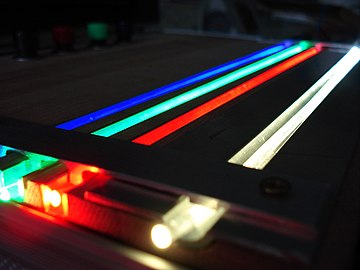
Partly laterally radiating polymer optical fibers (side light fibers )
.png)


Norms
Fiber optic cables or fiber optic cables are internationally standardized according to ITU-T G.651 to G.657, ISO / IEC 11801 and 24702 and IEC 60793, as well as nationally standardized according to DIN VDE 0888 (the standards DIN VDE 0899 parts 1–5 have been withdrawn).
literature
Physical basics:
- Govind P. Agrawal: Nonlinear Fiber Optics (Optics and Photonics). Academic Press, ISBN 0-12-045143-3 .
- Dieter Meschede: Optics, light and laser. Teubner, ISBN 3-519-13248-6 .
- Fedor Mitschke: Glass fibers: Physics and technology. Elsevier, Spektrum, Akad. Verlag, Heidelberg 2005, ISBN 3-8274-1629-9 .
- CR Pollock, Clifford Pollock, Michal Lipson: Integrated Photonics . Springer Netherlands, 2003, ISBN 1-4020-7635-5 .
- Bishnu P. Pal: Fundamentals of fiber optics in telecommunication and sensor systems . New Age International, New Delhi, 1992, ISBN 978-81-224-0469-2 .
- Claus-Christian Timmermann : Optical fiber . Vieweg / Springer, 1981, ISBN 978-3-528-03341-5 .
- Edgar Voges , Klaus Petermann: Optical communication technology: manual for science and industry . Springer, 2002, ISBN 3-540-67213-3 .
Technology:
- Volkmar Brückner: Elements of optical networks: Basics and practice of optical data transmission . 2nd Edition. Vieweg + Teubner, 2011, ISBN 3-8348-1034-7 .
- Dieter Eberlein: Fiber optic technology. Expert Verlag, Dresden 2003, ISBN 3-8169-2264-3 .
- D. Gustedt, W. Wiesner: Fiber optic transmission technology: Franzis' Verlag GmbH, Poing 1998, ISBN 978-3-7723-5634-6 .
- Rongqing Hui, Maurice S. O'Sullivan: Fiber optic measurement techniques . Elsevier Academic Press, 2009, ISBN 978-0-12-373865-3 .
- Christoph P. Wrobel: Optical transmission technology in practice: components, installation, applications. Hüthig, Bonn 2004, ISBN 3-8266-5040-9 .
- O. Ziemann, J. Krauser, PE Zamzow, W. Daum: POF manual: Optical short-range transmission systems . 2nd Edition. Springer, 2007, ISBN 978-3-540-49093-7 .
Web links
- Research around fiber optics Institute for Physics at the University of Rostock (Prof. Fedor Mitschke).
- Fiber optics Schäfter + Kirchhoff GmbH (including explanations on properties of MM, SM, PM-SM and photonic crystal fibers, PDF, English).
- Small fiber optic connector gauge Glasfaserinfo.de.
- Interactive representation of the chromatic dispersion Institute for Communication of the University of Stuttgart
Individual evidence
- ↑ Joachim Hagenauer: 50 Years of Information Technology - A Golden Age in Science and Technology. ITG ceremony in the Paulskirche Frankfurt on April 26, 2004 ( full text ( memento from July 19, 2011 in the Internet Archive )), quote: “He (Börner) is considered the visionary inventor of fiber optic transmission, a technology that is now the backbone of global Represents communication. "
- ↑ L. Blank, L. Bickers, S. Walker (British Telecom Research Laboratories): Long span optical transmission experiments at 34 and 140 Mbit / s . In: Journal of Lightwave Technology . tape 3 , no. 5 , 1985, pp. 1017-1026 , doi : 10.1109 / JLT.1985.1074311 .
- ↑ Heraeus developments. Retrieved August 9, 2017 .
- ↑ AT&T, NEC, and Corning Researchers Complete another Record Breaking Fiber Capacity Test. AT&T - News Room, May 11, 2009. Retrieved November 15, 2011.
- ↑ The information is inconsistent: At 114 GBit / s single data rate you need 280 channels for a total data rate of 32 TBit / s or you get 36.5 TBit / s with 320 channels.
- ↑ JD Jackson , C. Witte, K. Müller: Classical electrodynamics . 4th edition. Walter de Gruyter, 2006, ISBN 3-11-018970-4 , p. 448–450 ( limited preview in Google Book search).
- ^ A b Dieter Meschede: Optics, light and laser . Vieweg + Teubner, 2008, ISBN 978-3-8351-0143-2 , p. 100–103 ( limited preview in Google Book search).
- ^ Claus-Christian Timmermann: Optical fiber . Vieweg / Springer, 1981, ISBN 978-3-528-03341-5 , pp. 80 f .
- ↑ Rongqing Hui, Maurice S. O'Sullivan: Fiber optic measurement techniques . Elsevier Academic Press, 2009, ISBN 978-0-12-373865-3 , pp. 374-382 .
- ^ Edgar Voges, Klaus Petermann: Optical communication technology: manual for science and industry . Springer, 2002, ISBN 3-540-67213-3 , pp. 349 f .
- ↑ a b Fedor Mitschke: Glass fibers - physics and technology . Elsevier - Spektrum Akademischer Verlag, 2005, ISBN 3-8274-1629-9 , pp. 108-115 . ( 7.4 Geometry of the field distribution )
- ^ D. Marcuse: Loss analysis of single-mode fiber splices . In: The Bell System Technical Journal . tape 56 , no. 5 , 1977, pp. 703-718 ( archive.org [PDF]).
- ↑ Mode-Field Diameter Measurement Method. MM16, Corning Inc. 2001 ( PDF ( Memento of July 8, 2011 in the Internet Archive ))
- ^ CR Pollock, Clifford Pollock, Michal Lipson: Integrated Photonics . Springer Netherlands, 2003, ISBN 1-4020-7635-5 , pp. 166-174 . ( 2. Intrinsic Absorption Loss )
- ^ Nevill Francis Mott, Edward A. Davis: Electronic Processes in Non-Crystalline Materials . 2nd Edition. Oxford University Press, 1979, ISBN 978-0-19-964533-6 , pp. 272–304 ( limited preview in Google Book search). ( 6.7 Non-Crystalline Semiconductors - Optical Absorption )
- ↑ a b Fedor Mitschke: Glass fibers - physics and technology . Elsevier - Spektrum Akademischer Verlag, 2005, ISBN 3-8274-1629-9 , pp. 75-80 . ( 5th losses )
- ↑ a b c d Mike Gilmore: An Overview of Singlemode Optiocal Fiber Specifications. FIA - The Fibreoptic Industry Association 2004 (with additions 2010) ( PDF ( Memento of October 7, 2013 in the Internet Archive ))
- ↑ R. Krähenbühl, H. Schiess, C. Cecchin: Compatibility of Low Bend Singlemode Fibers. HUBER + SUHNER AG - Fiber Optics Division, White Paper 2010 ( PDF )
- ↑ M.-J. Li et al .: Ultra-low Bending Loss Single-Mode Fiber for FTTH. In: Journal of Lightwave Technology. Vol. 27, Issue 3, 2009, pp. 376-382 ( PDF ).
- ↑ a b A. B. Semenov, SK Strizhakov, IR Suncheley and N. Bolotnik: Structured Cable Systems . Springer, Berlin, Heidelberg 2002, ISBN 978-3-540-43000-1 , pp. 206–231 ( limited preview in Google Book search).
- ↑ Ramgopal Gangwar, Sunil Pratap Singh, Nar Singh: Soliton Based Optical Communication . In: Progress In Electromagnetics Research . tape 74 , 2007, pp. 157–166 , doi : 10.2528 / PIER07050401 ( PDF [accessed August 17, 2011]).
- ↑ Christopher Tagg: Soliton Theory in Optical Communications. In: Annual Review of Broadband Communication. International Engineering Consortium, 2006, ISBN 978-1-931695-38-1 , pp. 87-93 ( limited preview in Google book search).
- ↑ a b c Fedor Mitschke: Glass fibers - physics and technology . Elsevier - Spektrum Akademischer Verlag, 2005, ISBN 3-8274-1629-9 , pp. 93-98 . ( 6.2 The manufacture of glass fibers )
- ↑ a b c d e L. Cognolato: Chemical Vapor Deposition for Optical Fiber Technology . In: JOURNAL DE PHYSIQUE IV (Colloque C5, supplement au Journal de Physique 1) . tape 5 , 1995, p. 975-987 ( PDF ).
- ^ A b c d Phillip Bell, Todd Wiggs: Multimode Fiber and the Vapor Deposition Manufacturing Process (Outside Vapor Deposition vs. Inside Vapor Deposition). In: Corning Guide Lines. Volume 10, 2005. ( PDF ( Memento of September 3, 2009 in the Internet Archive ))
- ^ Bishnu P. Pal: Fundamentals of fiber optics in telecommunication and sensor systems . New Age International, New Delhi, 1992, ISBN 978-81-224-0469-2 , pp. 224–227 ( limited preview in Google Book search).
- ↑ O. Ziemann, J. Krauser, PE Zamzow, W. Daum: POF manual: Optical short-range transmission systems . 2nd Edition. Springer, 2007, ISBN 978-3-540-49093-7 , pp. 285–293 ( limited preview in Google Book search).
- ↑ Measuring Reflectance or Return Loss. The FOA Reference Guide To Fiber Optics, The Fiber Optic Association (FOA). Retrieved September 14, 2017.
- ↑ DJ Richardson, JM Fini, LE Nelson: Space-division multiplexing in optical fibers . In: Nature Photonics . tape 7 , no. 5 , 2013, ISSN 1749-4893 , p. 354–362 , doi : 10.1038 / nphoton.2013.94 ( nature.com [accessed November 23, 2017]).
- ↑ a b Mike Gilmore: UNDERSTANDING OM1, OM2, OM3, OS1, OS2 and more! FIA - The Fibreoptic Industry Association 2009 ( PDF )
- ↑ a b Russell Ellis: Bandwidth Potential of Optical Fibers. In: LANLine. 11/2006 ( PDF ( Memento from January 19, 2012 in the Internet Archive )).
- ↑ Merrion Edwards, Jean-Marie Fromenteau: Technology of the laser-optimized multimode fiber / paths of light. In: LANLine. 02/2006 ( PDF ).
- ↑ a b R. Elliot, R. Reid: 10 Gbits / sec and beyond: High speed in the data center. In: CABLING INSTALLATION & MAINTENANCE. 01/2008 ( PDF ( Memento from January 31, 2012 in the Internet Archive )).
- ↑ a b Grand Sauls: Data centers Networks. Falcon Electronics Pty Ltd, December 28, 2008 - Cisco Learning Network. ( PDF ).
- ↑ IEEE 802.3 Clause 38.4
- ↑ 40GBASE-FR Spec 40GBASE-FR Spec page 7
- ↑ 40GBASE-FR ( Memento of November 7, 2017 in the Internet Archive ) 40GBASE-FR page 4
- ↑ Dark Fiber - fiber optic infrastructure to wire yourself. Retrieved March 13, 2019 .
- ^ W. Daum, J. Krauser and PE Zamzow: POF - optical polymer fibers for data communication . 1st edition. Springer, 2001, ISBN 978-3-540-41501-5 , pp. 389 ( limited preview in Google Book Search).
- ↑ DIN VDE 0899-1 VDE 0899-1: 1987-12 . In: VDE VERLAG GMBH, Berlin-Offenbach . Retrieved November 21, 2011.