
flange


A flange is usually understood to mean an annular disk with the aid of which pipelines are connected to one another. Usually this ring is firmly attached to the end of a pipe. The two pipes are connected by means of screws , which are inserted through holes in the adjacent flanges, and nuts .
If a pipe is thickened at the end, such a ring located behind it can strike the end face of the thickening and transmit the screw forces to the pipe. Then it is a loose flange .
Instead of the tubes, it can also be shafts that are connected to one another in alignment. One such shaft connection is a flange coupling . Other parts that are mostly detachably connected to one another in machines and buildings are flanged to one another.
A built-in in a ring bearing ( sliding or roller bearing ) is used as a flange bearing , respectively. It is via the holes in the ring on the machine frame or on the wall of a bearing housing secured.
Flange connections can be detached non-destructively.
etymology
The word flange [en] is of late Middle High German origin and means "to protrude from a surface". Pipeline flanges protrude radially away from pipelines. It also explains that artisans may flanged something on a wall, as well as the belts, which an H-steel construction profile (the upper and lower end double-T-carriers ) form, and also the flanges (see FIG. Engl. Flange ) may be mentioned.
Examples of flange connections
- Connection of pipes,
- Bearing cover for fixing bearings in the associated housings and on the associated shafts .
- Connection of motors and gears,
- Fastening of rotor blades to wind turbines ,
- Connection of steel towers from several segments.
Flanges as standardized connecting elements for pipes

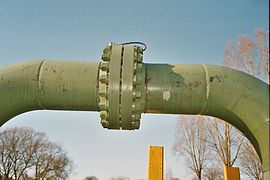
Connection of two pipes with disc-shaped flanges; Flanges welded to pipes; Flat seal between the flanges

loose flange behind thickened pipe end


The use of flanges is a method of detachably and tightly connecting pipe sections together. As a rule, a flat gasket is inserted between the flanges (both perforated), which are pressed together with screws and nuts. The flanges are mostly discs welded to the pipe ends. They belong to the pipeline parts ( fittings ).
Flanges are often cast on fittings and measuring devices . Flanges for pipelines are designated according to the nominal pressure and standardized by the EN 1092 series:
- EN 1092-1 steel flanges
- EN 1092-2 cast iron flanges
- EN 1092-3 flanges made of copper alloys
- EN 1092-4 aluminum alloy flanges
Flanges are made from all suitable and common types of stainless and carbon steel, such as 1.4541, 1.4571, F316L, F304L, WStE355, TStE355, LF2, 16Mo3, C22.8, P250GH, S235JRG2, RSt37-2. For example, a flange is manufactured according to the relevant standards DIN, EN, ANSI, GOST, JIS and other international norms and standards or according to customer drawings.
In the area of loose flanges (DIN 2641/2642 / EN1092-1 type 02), smooth flanges (DIN 2573/2576 / EN1092-1 type 01) and blind flanges (DIN 2527 / EN1092-1 type 05), cost reductions can be achieved, if, instead of the standard blade thickness, a reduced - but sufficient - blade thickness is used.
Flange types
There are different types of flanges that are used in different areas of application. For example, flanges can be welded or screwed to the pipe. Some flange types have a better stability behavior (low blade deformation with high screw forces) in order to meet special tightness requirements.
| designation | description | Designation according to EN | Designation according to the old DIN |
|---|---|---|---|
| Welding neck flanges | Flanges with a shoulder for welding , for example on a pipe . They are preformed from a steel blank by forging and then finished by turning and drilling . Larger flanges are also bent into rings from sectional steel and then welded. This type of flange is structurally particularly stable and is also used at high pressures. | Type 11 | DIN2627-DIN2638 |
| Slide-on welding flanges with shoulder | These are pushed onto the pipe and then welded to the pipe. In the ANSI area, they are also called slip-on flanges . | Type 12 | |
| Smooth flanges | These are pushed onto the pipe and then welded to the pipe. They are usually made from sheet metal . Larger flanges are bent into rings from flat steel and then welded. | Type 01 | DIN2573, DIN2576, |
| Blind flanges | Blind flanges do not have a central bore and are used for closing e.g. B. additional nozzles on pressure vessels or pipe ends. | Type 05 | DIN2527 |
| Threaded flanges | Instead of a welding attachment , this type of construction has an internal thread into which the pipe is screwed. | Type 13 | DIN2566 |
| Loose flanges | This design is only pushed loosely onto the pipe. The actual mounting on the tube assumes the then to be welded Vorschweißring or stub end TYPE 04. They are also used for molded flange 02. TYPE This type is used when the position of the pitch circle of the mating flange until the final assembly can be defined. | DIN2641, DIN2642, DIN2565, | |
| Block flanges | This design consists of a forged or a cast block. The associated screw holes have an internal thread . Such flanges are mainly welded to pressure vessels as pipe sockets and are used to fasten sight glasses . | ||
| Apparatus flanges | They have the same function as normal flanges, but are preferably used on boilers , pressure vessels and the like. You can therefore have other flange leaf thickness dimensions, e.g. B. with cast housings. | ||
| SAE flanges | SAE flanges are used in various designs in oil hydraulics . These flange fittings are also known as CAT flanges as they were developed by Caterpillar in the United States . SAE flanges are divided into 3000, 6000 and 9000 PSI pressure levels. An example of SAE flanges is the F37 flange. | ||
| Vacuum flanges | Vacuum flanges are used for the detachable connection of vacuum vessels . They are available as small flanges , clamp flanges and CF flanges . | ||
| Transition flange press fittings GD | The design of this flange enables a transition from a press fitting system GD to the flange system. Most of them are cast and have an M-contour. |
Dimensional ranges
A small selection of possible dimension ranges. Larger dimensions are of course also possible.
| Flange type | Range of dimensions |
|---|---|
| Blind flanges | DN10 - DN2500 ½ ”- 24 ″ |
| Threaded flanges with shoulder | DN15 - DN150 ½ ”- 24 ″ |
| Flanges smooth | DN10 - DN2500 |
| Welding neck flanges | DN10 - DN2500 |
| loose flanges, smooth collars | DN10 - DN2500 |
| loose flanges, welding necks | DN10 - DN2500 |
| Welding flanges with shoulder | Example DN15 - DN2500 |
| Lap joint flanges | ½ "- 24" |
| Socket welding flanges | ½ "- 3" |
Norms
The table shows a comparison of the previous DIN standards for flanges and the flange types in the currently valid DIN EN 1092-1: 2013-04. Various flange standards (in some cases one standard for each nominal pressure) were combined in one standard.
| previous norm | description | Flange type according to DIN EN 1092-1 |
|---|---|---|
| DIN2527 PN6 - PN100 | Blind flanges | Type 05 |
| DIN2566 PN10 - PN16 | Threaded flanges with shoulder | Type 13 |
| DIN2627-DIN2638 | Welding neck flanges | Type 11 |
| DIN2641; DIN2642 | Loose flanges, welding necks, smooth collars | Type 02,33,32 |
| DIN2655; DIN2656 | Loose flanges, smooth collars | Type 02,33,32 |
| DIN2673 | Loose flanges with welding neck | Type 04,34 |
| DIN86029; DIN86030 | Welding flanges with shoulder (withdrawn!) | |
| EN1092-1 / 01 | Smooth flange for welding, PN2.5 - PN100 | Type 01 |
| EN1092-1 / 02 | Loose flange for types 32-37, PN2.5 - PN40 | Type 02 |
| EN1092-1 / 05 | Blind flange, PN2.5 - PN100 | Type 05 |
| ISO 7005-1 | Metal flanges - steel flanges, reference to EN1092-1! | |
| ISO 7005-2 | Metal flanges - cast iron flanges, PN2.5 - PN50 | |
| ISO 7005-3 | Flanges made of metal - copper alloys and composite materials, PN2.5 - PN50 |
Flanged connection of a pipeline

Blind flange at the end of a pipeline

Hose fitting SAE 100R15, nominal size 32, 6000 PSI


Web links
Individual evidence
- ↑ Duden | Flange | Spelling, meaning, definition, origin. Retrieved March 31, 2017 .
- ↑ Günther Holzmann, Heinz Meyer, Georg Schumpich: Technical mechanics: Part 3: Strength theory . 7th edition. S. 178-180, 81 .
- ↑ a b c Manfred Pister, Jörn Ohmann: Exhaust system for diesel vehicles Exhaust system for diesel vehicles . DE102013016235 A1, April 2, 2015 ( google.no [accessed on March 31, 2017]).