Diplexer
A diplexer is an electrically passive assembly in high-frequency systems with three gates , which is used to separate an electromagnetic power described as a guided wave , usually in a waveguide , depending on the frequency between two gates or to combine it in the opposite operating direction on a gate. The diplexer is a special type of crossover network.
An extension of the diplexer to four ports is called a triplexer, this can separate or combine three different frequency ranges.
Applications
Practical applications of the diplexer are in the areas of radio technology and radar technology . With a diplexer, it is possible to operate a radio transmitter and a radio receiver with different transmission and reception frequencies on just one antenna , which serves as a transmission and reception antenna. The diplexer separates the transmission frequency from the different reception frequency, which enables simultaneous transmission and reception without the much more powerful transmitter overriding the sensitive radio receiver.
In contrast to a diplexer, a duplexer is a changeover switch that allows either only the radio transmitter or only the receiver, but never both at the same time, to be in operation. In the so-called duplex mode , the same transmission and reception frequency can be used.
Another application of diplexers is the separation of individual frequency bands for receiving devices in different frequency ranges. In receiving systems, for example, several narrowband antennas can be combined in terms of frequency, so that in total a larger bandwidth or the reception of several different frequency ranges can be covered. This property is important for some head-end stations in cable networks .
construction
Diplexers can be implemented in various ways.
filter

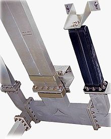
In principle, a diplexer can be constructed by combining two passive and different filters , for example in the form of a waveguide filter with dielectric resonators in the figure opposite . The two filters, recognizable in the metallic housing as the lower and upper horizontal line, are selected or adjusted in their transmission behavior so that they each allow the desired frequency range in the range of a few GHz to pass. The two filters are interconnected at the common connection, in the figure this is the connection on the right-hand side, which is routed to a common antenna, for example. The two connections on the left represent the connections filtered in the frequency range and go, for example, to the transmission stage and a reception stage in different frequencies.
In addition, at lower frequencies, for example at a few MHz, diplexers can be implemented as filters with discrete electronic components made of coils and capacitors . The assemblies formed in this way are then usually referred to as a crossover network.
running time
A diplexer, which works on the basis of the transit times, consists of two successive directional couplers that separate the waves in each direction. Between these two directional couplers there are two waveguide segments of different lengths, usually in the shape of a U and referred to as a detour line. The length of the two waveguides determines the transit time of the wave through the respective section, whereby a phase shift can be achieved which in the case of the second directional coupler leads to a cancellation due to destructive interference . The advantage is the high performance stability of such a diplexer and, on the other hand, a simple frequency change is also possible by changing the lengths of the detour lines.
The length of the two detour lines must be dimensioned in such a way that summation takes place on the respective output line in one frequency and cancellation in the second frequency. A diplexer works most effectively when the tunable detour line meets the following conditions at the same time:
- The phase shift for the A frequency is 0 °
- The phase shift for the B frequency is 180 °
The frequency spacing between the two transmission frequencies is specified by the design. In practice, these detour lines are dimensioned with a multiple of the wavelength, since smaller phase differences then multiply and the diplexer receives a narrower transmission curve. The transmission frequencies are thus specified in that the same waveguide length must have an even integral multiple for one frequency and an odd multiple of half the wavelength for the second frequency.
swell
- Otto zince , Heinrich Brunswig: high frequency technology . 6th edition. Springer, 2000, ISBN 978-3-540-66405-5 .
- Albrecht Ludloff: Practical knowledge of radar and radar signal processing . 4th edition. Vieweg + Teubner, 2009, ISBN 978-3-8348-0597-3 .
- Joseph J. Carr: RF Components and Circuits . Newnes, 2002, ISBN 978-0-7506-4844-8 .

