
Cooling fin


Cooling fins (also cooling fins called, engl. Cooling fins ) are used to increase the surface area to a body, the heat transfer to the surroundings and thus the cooling to improve. Ribbed surfaces can be part of the heat-generating machine itself, for example on an engine block , or they can be designed as a separate component. Such heat sinks can in turn be in direct mechanical contact with the heat source or can be connected to it via an additional medium, as is the case with water cooling , for example . Heat sinks passively or as part of active cooling ensure that machines, electrical and electronic systems are kept at a permissible operating temperature.
The cooling fin was invented and used for the first time by the Austrian engineer Franz Pichler to cool dry transformers .
Mode of action
The heat flow from a surface to the surrounding cooling medium depends on the temperature difference, the contact area and the heat transfer coefficient according to the following relationship

With
- = Heat flow [W]
- = Heat transfer coefficient [W / (m 2 · K)]
- = Contact area [m 2 ]
- = Body temperature [° C]
- = Temperature of the cooling medium [° C]


The amount of heat dissipated can therefore be increased by increasing the contact area A. The heat flow does not increase proportionally to the increase in area, but is dependent on the fin efficiency (see below ).
The ribs mean an - mostly undesirable - increase in weight and external dimensions. With targeted use, however, in addition to cooling, they can also increase the mechanical strength of a component or reduce the sound radiation of a machine (by suppressing surface vibrations).
Heat flow through a fin

With constant heat conduction along a rod or a rib, a thermal equilibrium is established between the heat flow that enters the rod and the heat flow that is dissipated via the surface to the environment.
In the following we consider the mathematically simplest case: a rod or a rib with a rectangular cross-section, a constant ambient temperature and a constant heat transfer coefficient. If one considers the rod element dx, the following equilibrium condition results:
Incoming heat flow:

Exiting heat flow:

The heat transfer on the surface to the environment is:

here mean:
- = Heat transfer coefficient [W / m 2 · K]
- = Circumference of the rib [m]
- = Rib cross-section [m 2 ]
- = Thermal conductivity of the material [W / K · m]
- = Ambient temperature [° C]


The heat balance results in:

This leads to the differential equation for the fin temperature:

Here mean:
- ΔT = T - T u

The solution of the differential equation leads to the following results (the heat flow through the face at the fin end is neglected):
Temperature profile along the rib:

.PNG)
Temperature at the end of the rib:

With

the heat flow through the base of the fin follows:

Here mean:
- L = length of the rib
- ΔT 1 = rib excess temperature at the rib base
- sinh, cosh, tanh: hyperbolic functions
The cooling effect of a rib therefore decreases as the temperature drop from the rib base to the rib tip increases. According to the above equations, the dimensionless parameter (m · L) is decisive for this temperature drop .
example
The figure on the right shows the rib excess temperature ΔT (standardized to 1) on a rib of length L for various values of the parameter (m · L). The parameters (m · L) were for a 0.5 mm thick and 30 mm high rectangular rib (A = 15 mm²; U = 61 mm) made of four different materials in the air flow with a heat transfer coefficient of h = 15 W / m 2 / K calculated. With the copper and aluminum fins (m · L = 0.37 and 0.52, respectively), the temperature drop to the fin tip is less than 10%, these fins have an almost ideal cooling effect. In the case of the plastic rib (m · L = 14), however, the excess temperature of the rib falls to less than 5% of the initial value after a quarter of the length (L / 4); this rib is practically ineffective for cooling.
Fin efficiency

The ribs efficiency is defined as the ratio of the heat flow , which the rib actually emits an ideal heat flux that would make the rib when it over its entire length, the initial temperature T 1 possessed (at an infinitely high thermal conductivity):


With
- h = heat transfer coefficient [W / m 2 K]
- U = circumference of the rib [m]
- L = length of the rib [m].

For a rectangular fin, a constant heat transfer coefficient and a constant ambient temperature, the following was derived:

The fin efficiency is thus calculated as:

With
- the characteristic value in [1 / m]
- Hyperbolic tangent .

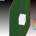
Example: Influence of the rib thickness on the efficiency
The images below show the calculated temperature distribution on two aluminum heat sinks. By increasing the rib thickness from 0.2 mm (left image) to 2.0 mm (right image), the temperature drop to the rib tip was significantly reduced and the rib efficiency increased.

Cooling fins with a low efficiency

Cooling fins with a high degree of efficiency


Rib density

A higher fin density leads to an enlargement of the heat dissipation area and thus to a higher efficiency for the cooling. On the other hand, a higher rib density results in narrower rib channels with increasing flow resistance. This leads to a so-called by-pass effect: the flowing air is 'displaced' from the rib channels and increasingly flows unused past the ribs. The cause lies in the wall friction with the formation of a flow boundary layer . The thickness of the boundary layer depends on the Reynolds number , see also boundary layer equations . The two pictures below show a numerical simulation of this by-pass effect.

Air flow through a heat sink with sufficient fin spacing
Air flow through a heat sink with insufficient fin spacing


literature
- Walter Wagner: heat transfer. 6th edition. Vogel Buchverlag 2004, Kamprath series, ISBN 3-8023-1974-5 .
- Allan D. Kraus, Bar-Cohen Avram: Thermal Analysis and Control of Electronic Equipment. Hemisphere Publishing Corporation 1983, ISBN 0-07-035416-2 .
- DQ Kern, AD Kraus: Extended Surface Heat Transfer. McGraw-Hill, New York 1972, ISBN 0-07-034195-8 .
Web links
- Estimating Parallel Plate-Fin Heat Sink Thermal Resistance
- Introduction to the physics of cooling electronic systems (PDF file; 358 kB)
- Lecture University of the Federal Armed Forces Munich (PDF file; 2.23 MB)
Individual evidence
- ^ German biography - Pichler, Franz. In: deutsche-biographie.de. Retrieved August 15, 2016 .
- ^ Biography from the Austrian Biographical Lexicon. (PDF) In: biographien.ac.at. Retrieved August 15, 2016 .