Sheath current

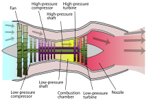
As turbofan (also by-pass, cold air, secondary, secondary current) is in a turbofan engine designated that air stream from a single or multi-stage axial fan (the fan speeds up stage) and concentric to the core engine over is passed and the not in the gas turbine on the combustion process is involved and the power output of the turbine stages. In the engine it flows around the core engine, and after exiting the engine it encases the flow of hot gas from the core engine.
Origin of the service to the company
The primary core flow , i.e. the flow that passes through the compressor , the combustion chamber and the turbine , maintains the combustion process . After combustion, this core flow expands in the high-pressure and finally in the low-pressure turbine stages, releasing part of its energy - to operate the compressor of the core engine and to operate the fan for the bypass flow.
Usual designs
Two-shaft engines with a short "high pressure shaft" to which all the compressor and turbine stages of the core engine are attached and a "low pressure shaft" to which only the fan and a few turbine stages are attached to drive the fan are common. The low-pressure shaft runs coaxially through the hollow high-pressure shaft, which enables it to transfer the rotary power from the turbine stages located at the very rear to the fan located at the very front. The impeller of the fan has a much larger diameter than the compressor stages behind it. The split into core and bypass flow takes place after the fan stage, the air near the hub enters the compressor housing of the core engine, while the accelerated bypass flow flows through an aerodynamically designed, ring-shaped nozzle channel between the bypass housing and the outside of the core engine. Depending on the design of the engine nacelle, this ring channel ends after a short distance or it is guided over the entire length of the engine in a covering that extends behind the thrust nozzle of the core engine.
Alternatively, a separate low-pressure shaft can be dispensed with if the high-speed rotating high-pressure shaft of the core engine transfers the rotary power for the significantly slower rotating fan to it via a gear unit ( “geared turbofan” design ).
The aft-fan design also manages without a low-pressure shaft and even without a gearbox , in which the fan is not in front of the core engine, but behind it, directly on the fan-driving turbine stage.
Bypass ratio
In modern turbofan engines in commercial aviation is the by-pass ratio 1 to 10: 5: 1 (secondary flow to core flow). With current geared drives such as the Pratt & Whitney PW1000G , the ratio is up to 12: 1. The thrust of the bypass flow makes up around 80% of the total thrust in modern bypass flow engines.
In military bypass engines in combat aircraft, the bypass ratio is significantly lower, sometimes less than 1: 1.
If the core engine is clearly separated from the fan area and its main task is to supply the fan-driving (low-pressure) turbine stages with power in the form of a fast, pressurized hot gas, the core engine is sometimes also called a "(hot) gas generator" .
advantages
Airplane engines with a bypass flow have a number of advantages: They consume less fuel , since only part of the air is used for the combustion process, the other, much larger part, is accelerated only by a jacketed propeller ; they are quieter because the bypass flow with all its fairings is sound-insulating around the gas turbine and, after exiting, around the hot gas jet of the core engine; they usually have a longer service life, since only about 20% of the generated thrust is generated by components that are subject to high thermal and mechanical loads.
Web links
- State-of-the-Art Subsonic Engine SFC , NASA diagram of specific fuel consumption (SFC) of different jet engine designs in the subsonic range, English language
