Matched Z transformation
The matched z-transform method ( English matched z-transformation , in German approximately matched Z-transformation and also as a pole-zero mapping hereinafter) in the signal processing a transformation - a conversion mode in mathematics - between the time-continuous and time discrete representation of system functions. It plays a role in digital signal processing and control theory , as it enables implementation in the system description between analog, continuous systems and digital, discrete systems. Transformations with a similar scope are the bilinear transformation and the momentum invariance method .
motivation
In signal processing and control engineering, for implementation in the field of digital signal processing, there is a requirement to convert given time-continuous transfer functions G (s) from linear, time-invariant systems into time-discrete transfer functions H [z] with behavior that is as identical as possible. The transfer function G (s) can describe an analog filter , for example , and H [z] represents a time-discrete transfer function derived from the analog filter, which describes an equivalent digital filter .
Compared to methods similar to the bilinear transformation, the matched Z transformation offers the advantage of avoiding non-linear distortion of the transfer functions from G (s) to H [z] in the transmission range. The aliasing effects caused by this method in the time-discrete system are disadvantageous .
description
The description of the system functions of continuous-time systems takes place in the so-called s-level , in the complex level , and their analysis is carried out by means of the Laplace transform . In the case of time-discrete systems, the representation takes place in the so-called z-plane and the analysis takes place by means of the Z-transformation . In the case of linear, time-invariant systems - these systems are required when applying the matched Z transformation - the transfer function G (s) can be written as a rational function as:
With zeros and poles . The factor represents an amplification factor. In the matched Z transformation, all pole and zero positions are associated with the relationship
implemented. The parameter T represents the temporal sampling interval (period duration ) of the time-discrete system. The time-discrete transfer function H [z] is thus formed as:
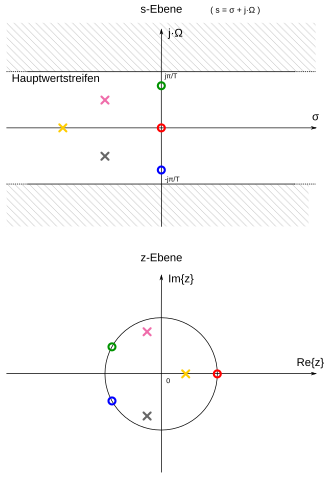
The transformation process is qualitatively sketched in the adjacent figure on a transmission system with three zero and three poles, the transition of the individual points is shown by the color correspondence. If in the time-continuous system not all poles and zeros in the s-plane lie within the non-hatched area designated as the main value strip, aliasing occurs in the time-discrete system.
The gain factor in the discrete-time system is selected by comparing it at characteristic frequency points. For example, with a low-pass filter for the direct component at the frequency 0 s −1 . In order to ensure the same delay times in the time-discrete filter, it may also be necessary to add further poles or zeros at .
literature
- Alan V. Oppenheim, Ronald W. Schafer: Discrete-time signal processing . 3. Edition. Oldenbourg, Munich 1999, ISBN 3-486-24145-1 .
- Won Young Yang: Signals and Systems with MATLAB . Springer Verlag, 2009, ISBN 978-3-540-92953-6 , pp. 291 to 294 .
Individual evidence
- ^ D. Rowell: Signal Processing - Continuous and Discrete - Lecture Note 19 (OpenCourseWare). (PDF; 244 kB) Massachusetts Institute of Technology (MIT), 2008, accessed on February 4, 2013 .


![{\ displaystyle H [z] = K '\ cdot {\ frac {\ prod _ {k = 1} ^ {M} \ left (ze ^ {n_ {k} T} \ right)} {\ prod _ {k = 1} ^ {N} \ left (ze ^ {p_ {k} T} \ right)}}}](https://wikimedia.org/api/rest_v1/media/math/render/svg/8e0b31010636bcb8d37de6452717b209e061df61)

