Miller effect
The effective increase in parasitic capacitance between the output and the inverting input of a voltage amplifier is referred to as the Miller effect . This effect is mostly disruptive, but can also be used to advantage to generate larger effective capacitance values. The effect is named after John Milton Miller , who discovered it in 1919. A generalization of the Miller effect is the Miller Theorem .
description

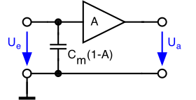
In the upper picture, an amplifier with the voltage gain A = U a / U e is shown, with a Miller capacitance C m between the input and output . This capacitance acts at the input of the amplifier with the size C e , which depends on the gain A and is given by the following expression
For an inverting amplifier, the gain is negative, so there is an increase in capacitance. It now holds that A <0:
and the Miller capacitance appears at the input increased by the factor (1+ | A |).
For any amplification A , the Miller capacitance can be replaced by the corresponding capacitance at the input of the amplifier, whereby the effect of the capacitance between the input terminals becomes clear. This is shown in the picture below.
Miller effect in transistor circuits
In order to implement a voltage amplifier with transistors , the emitter circuit is used (or the analog source circuit for field effect transistors ), which works inverting. Parasitic capacitances always exist between the connections of the transistors, such as the collector-base capacitance C CB in the bipolar transistor or the gate-drain capacitance in the MOSFET, so that the Miller effect also occurs here.
An emitter circuit is shown in the picture on the right, a Miller capacitance C m being explicitly drawn in. This capacitance is representative of the parasitic capacitance already present in the transistor. Due to the Miller effect, this capacitance appears to be greater at the input by the amount of amplification.
The effective capacitance at the input of the amplifier C in is thus given by the following expression
where C m in this case represents the collector-base capacitance and A is the gain of the emitter circuit, which is negative.
This effect is usually undesirable because it limits the use of the emitter or source circuit to low to medium frequencies . With operational amplifiers, on the other hand, this effect is used for simple frequency compensation . In the case of power MOSFETs and ring oscillators , the effect extends the switching times considerably, which ultimately leads to a low cut-off frequency .
A cascode circuit is an effective means of suppressing the Miller effect, as the cascode reduces the effect of the amplifier output on the input.
If an inductance is connected to the amplifier output , the Miller capacitances can cause an oscillation instead of a negative feedback. See Miller effect oscillator .


