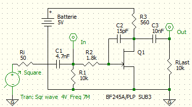
Miller integrator
The Miller integrator is an electrical circuit for generating linearly increasing signals. The circuit can be used as a sawtooth generator , for relaxation oscillations , and as a triangle generator . A circuit for relaxation oscillations based on the Miller integrator is the Miller-Transitron . An integral controller in analog technology is usually implemented with a Miller integrator.
Circuit description
The Miller integrator consists of the charging resistor R 2 , the integration capacitor C 2 and the JFET Q 1 . There is a square wave voltage at the input In. Substituted them from negative to positive voltage so is C 2 over R 2 reloaded. The JFET Q 1 linearizes the charging curve. Whenever the gate gets a little more positive, the drain gets a little more negative. The voltage across the capacitor C 2 remains the same, and so does the charging current. For an ideal Miller integrator, the amplifier's input resistance and gain are infinite. An operational amplifier fulfills these conditions very well at low frequencies; a JFET is suitable for higher frequency applications.
There is an internal capacitance between the base and collector of a bipolar transistor or between the gate and drain of an FET. The capacitance value ranges from a few femtofarads for MOSFET tetrodes, to a few picofarads for low-power transistors to a few nanofarads for power MOSFETs . The Miller effect describes the effect of this internal capacity.
References, literature
- SW Amos, RS Amos: Newnes Dictionary of electronics . Butterworth Heinemann, 1999. Link
- Schröder, Feldmann, Rommel: Electrical communications engineering Volume III . Verlag für Radio-Foto-Kinotechnik, Berlin-Borsigwalde 1972.
