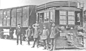
Ottensener Industriebahn 3
| Ottensener Industriebahn 3 | |
|---|---|
|
historical photo
|
|
| Numbering: | Ottensener Industriebahn 3 |
| Number: | 1 |
| Manufacturer: | Borsig |
| Year of construction (s): | 1910 |
| Retirement: | before 1945 |
| Type : | B n2t |
| Gauge : | 1000 mm ( meter gauge ) |
| Total wheelbase: | 1,100 mm |
| Empty mass: | 13.5 t |
| Service mass: | 16 t |
| Friction mass: | 16 t |
| Wheel set mass : | 8 t |
| Top speed: | 25 km / h |
| Starting tractive effort: | 18.5 kN |
| Driving wheel diameter: | 650 mm |
| Control type : | Heusinger |
| Cylinder diameter: | 210 mm |
| Piston stroke: | 300 mm |
| Boiler overpressure: | 14 bar |
| Grate area: | 0.6 m² |
| Evaporation heating surface: | 16 m² |
| Water supply: | 0.75 m³ |
| Fuel supply: | 2 × 0.6 m³ |
| Brake: | Vapor barrier handbrake |
The narrow gauge - tram locomotive Ottensener industry lane 3 was the locomotive factory Borsig for Ottensener Industriebahn made. It entered service in 1910 and was the company's first steam locomotive. The dates of use of the locomotive are not exactly verifiable; it was probably taken out of service before 1945.
history
Before 1910, the Ottensener Industriebahn bought two motor locomotives in 1904 and 1905 to move the freight wagons onto the narrow-gauge tracks.
Locomotives of this type are said to have been produced as early as 1898. Quantity and recipient are not known.
The locomotive had a standing smock tank and therefore a small wheelbase, a stocky exterior and almost no overhanging masses. The control elements were duplicated so that the train driver could change the operator position when changing the direction of travel. The locomotive had a double-stacked pulling and buffing device in order to couple standard-gauge freight cars both directly and on roller stands . With another coupling option, individual roll stands could be coupled with a rod.
In 1925 it was still in operation, after which no more data can be found. It can probably be assumed that locomotive 3 was retired before 1945.
technology
The box locomotive was completely disguised. For maintenance of the engine it had numerous flaps in the side walls. The outer frame contained a water tank with a capacity of 0.75 m³.
The outer jacket of the standing kettle was connected to a bottom ring at its lower end. Due to its design, the boiler had a large water space and, like the steam railcars, was suitable for a rapid development of steam. Under the boiler was the ash box, the flap of which could be operated from the driver's cab. A sieve should prevent pieces of coal from falling out.
The design of the boiler gave the operating personnel a good overview of the route. The cylinders were outside between the frame and the fairing, which made maintenance work easier. The power was transmitted to the axles via drive rods, coupling rods and Hall cranks .
The exhaust steam from the locomotive was fed into a condenser mounted on the roof. After flowing through the multi-curved tube bundle, it was returned to the water tank.
The locomotive was closed all around with openable glass windows on both the sides and the end walls. The two 0.6 m³ coal boxes were filled through the front wall sliding window. The locomotive was equipped with a whistle and a Latowski bell .
literature
- Dirk Oetzmann: The Hamburg narrow-gauge railways . Association of traffic amateurs and museum railways V., Hamburg 2010, ISBN 978-3-923999-77-4 , pp. 52-53 .
- Walter Hefti: Tramway Locomotives . Birkhäuser Verlag, Basel 1980, ISBN 3-7643-1159-2 , p. 66 .
Web links
Individual evidence
- ↑ a b c Dirk Oetzmann: The Hamburg narrow-gauge railways . Association of traffic amateurs and museum railways V., Hamburg 2010, ISBN 978-3-923999-77-4 , pp. 52-53 .
- ^ Walter Hefti: Tramway Locomotives . Birkhäuser Verlag, Basel 1980, ISBN 3-7643-1159-2 , p. 66 .
