
Schuler pendulum
A Schuler pendulum ( compensating pendulum , minimum pendulum l) is a (physical) pendulum used for precision pendulum clocks , the center of gravity of which is at a distance from the pendulum axis of rotation that corresponds to the radius of inertia of the pendulum body based on a parallel axis through the center of gravity and that is driven by electromagnetic means. Such pendulums are based on suggestions by Maximilian Schuler , which he presented in two patents.
Note : The Schuler pendulum described here must be distinguished from the hypothetical pendulum of the same name, which is important when applying gyroscopic theory to navigation problems (see Schuler period ). The investigations were also carried out by Max Schuler.
The precision pendulum clocks designed and built by Riefler and Strasser at the end of the 19th and beginning of the 20th centuries showed astonishing accuracy thanks to measures such as free escapements , compensation pendulums , operation in a hydrogen atmosphere and temperature control. The pendulum suspension was a weak point . In precision pendulum clocks, this is designed as a pendulum spring (thin leaf spring) or as a blade bearing. Pendulum springs are subject to changes in length due to the effects of temperature or material fatigue occurring over time, while cutting edge bearings are subject to a certain amount of wear due to abrasion. This leads to changes in the length of the pendulum and thus to a change in the period of oscillation , which in turn results in clock rate deviations . Schuler wanted to remedy this.
Furthermore, according to his intention, the pendulum should swing as freely as possible and the periodic energy supply necessary to maintain the pendulum oscillation should no longer take place mechanically by means of an inhibition, but rather electromagnetically without interference.
Pendulum
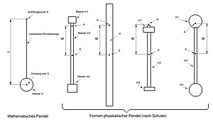
Pendulum shapes
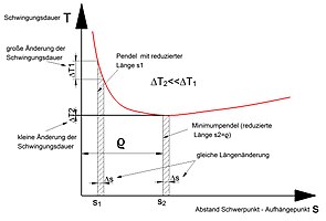
Minimum of the period of oscillation


The pendulums used for pendulum clocks (also for precision clocks ) can be viewed approximately as mathematical pendulums (pendulum rod is assumed to be massless). Their oscillation period is:


= Pendulum length, = acceleration due to gravity.


The period of oscillation is independent of the mass of the pendulum body and is only determined by the pendulum length.
The period of oscillation of physical pendulums is calculated using the same formula, except that instead of the pendulum length, the reduced pendulum length must be used. This depends on the moment of inertia of the pendulum (i.e. on its mass and its distribution).


= Moment of inertia of the pendulum in relation to an axis running through the center of gravity S (parallel to the pendulum rotation axis ), = pendulum mass, = distance of the center of gravity S from the rotation axis A (suspension point) of the pendulum.


The reduced pendulum length runs through a minimum depending on . The minimum is

corresponds to the radius of gyration of the pendulum in relation to its center of gravity. In the vicinity of this minimum, the reduced pendulum length changes only slightly when there is a change in (e.g. when the pendulum spring is stretched) and thus also the period of oscillation changes only slightly (see figure). It is therefore advisable to choose the same as the radius of gyration.

That is why Schuler suggested building precision pendulum clocks with a pendulum designed in this way. With the same change in length of the pendulum spring or the cutting edge bearing, a Schuler pendulum can achieve a lower rate deviation of the clock compared to the mathematical pendulum.
However, it must be taken into account that the effects of changes in length of the pendulum body (e.g. due to temperature influences) cannot be eliminated in this way, only those of the pendulum spring or the cutting edge bearing. Changes to the pendulum body lead to changes in the moment of inertia, thus to a different reduced pendulum length and therefore to rate deviations. They must be minimized by other measures (e.g. compensation pendulum).
example

Example pendulum
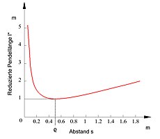
Course of the reduced pendulum length


A pendulum consisting of two cylindrical masses of equal size (total mass ) with the radius , which have the same distance from the center of gravity (assuming a massless connection), has the moment of inertia related to the center of gravity


The variants marked a and b in the figure are equivalent because of the identical moment of inertia.
If you set and , the minimum for is at


The suspension point is in the center of one cylindrical mass (see picture variant c).
If, as is usual with pendulum clocks, the period of oscillation of the pendulum is to be seconds (then the time display is switched every second; see seconds pendulum ), the reduced pendulum length must show the value . From the formula for the reduced pendulum length


there is only a slight deviation from the required values for the selected values . If, for example, it was desired, this reduced pendulum length could be realized with the underlying constellation, but the minimum condition would not be fulfilled (see figure). Both aspects must therefore always be taken into account when designing the pendulum.

If, for example, one assumes an increase in length both for this pendulum and for a mathematical second pendulum , the result is a corresponding change in according to the formula. With the help of the oscillation equation one finds that the clock with the mathematical pendulum lags behind by 4.3 seconds a day, while for a clock with a Schuler pendulum only 0.0008 seconds result!


Pendulum drive

Drive coil

Pendulum drive


With the Schuler pendulum, the pendulum drive is electromagnetic. The pendulum has a horseshoe magnet that moves relative to a fixed coil (see pictures). The coil is wound in the shape of a figure eight. In all sections of the coil winding shown in red, the current flows in the same direction, which is determined by the voltage applied to the coil connections. The winding strands shown in red are the effective winding sections, since only they exert a force on the magnet when current flows.
The horseshoe magnet is very narrow and has a small air gap so that the magnetic field is almost homogeneous and limited to the air gap. When current flows through the coil, it only exerts a force (Lorentz force) on the magnet (and thus on the pendulum) if the effective sections of the winding are located in the air gap of the magnet. This ensures that the drive pulse on the pendulum is largely independent of the switching times of the coil current (which are uncertain with spring contacts), which must be assumed for the constant oscillation period of the pendulum (and thus a high accuracy of the clock). It is only necessary that the current is switched on before the coil enters the air gap of the magnet and switched off after it leaves. As is usual and practical with pendulum clocks, the energy is supplied in the area of the (vertical) central position of the pendulum, whereby the direction of the current must be switched depending on the direction of oscillation of the pendulum.
In his patent specification, Schuler assumed that the switching of the current pulses would be done with the help of a contact spring (leaf spring) actuated by the pendulum, but left other options open. The spring circuit would have severely impaired the free pendulum oscillation. A contactless method was therefore chosen for the later implementation.
Schuler watches
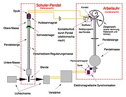
Schuler pendulum with work clock

Schuler clocks have been built and tested as test clocks (among others by the Riefler company).
The switching of the current pulses was implemented with a light barrier controlled by the pendulum (i.e. contact-free without spring contacts). Clocks with self-control and those with control via a work clock (“slave clock ”, similar to the Shortt clock ) were built. In both cases, the Schuler pendulum could swing largely freely and independently of the components used to display the time.
In the self-controlled variant, the light barrier signals were used to trigger the current pulses and to control an electrically operated external pointer mechanism.
The version with a work clock used a modified precision pendulum clock (e.g. with Riefler gravity escapement), which was synchronized with the light barrier signals of the Schuler pendulum swinging separately in a hydrogen atmosphere and which in turn supplied current impulses to control it and took over the time display. The electromechanical generation of the current pulses by the work clock disturbed its pendulum oscillation slightly, but this was constantly corrected by the synchronization.
School clocks could not prevail. This was due in particular to the electronics (light barrier, tube amplifier), which were prone to failure at the time, and the resulting maintenance effort. Precision pendulum clocks were built by the Riefler company until 1965 (with a Riefler pendulum ). Schuler pendulums were not used for this. Then the quartz watches began their triumphant advance.
Individual evidence
- ↑ Max Schuler: Pendulum for timing purposes. Retrieved on April 27, 2019 (click on "Load full document" after calling up).
- ^ Max Schuler: Electrically powered pendulum for timing purposes. Retrieved on April 27, 2019 (click on "Load full document" after calling up).
- ↑ Gengler: Precision time measurement and Schuler pendulum. Retrieved April 27, 2019 .
- ^ Weber: The Schulersche equalizing pendulum. Retrieved April 27, 2019 (scroll down after access).
- ^ Gockel / Schuler: About a new self-propelled Schuler watch. Retrieved April 27, 2019 .