
Roller coaster


A roller coaster chassis has the task of guiding the movement of the car - often part of a carriage set - of a roller coaster safely along the mostly two rail (s) .
Railway wagons roll on the two-rail track per axle on a set of two wheels that are firmly connected by a material axle. The force of gravity presses the train into the (transversely) horizontally lying track, flanges form stops against sideways movement out of the track. Conical wheel treads and lateral play, the shoulders of the rails inclined somewhat transversely to one another, and the elevation of the track in curves refine the guidance. The form fit with a certain amount of play only results from the interaction with the contact pressure on the track, essentially through gravity.
However, the undercarriage of roller coaster cars has the task of transmitting forces in 3 directions between the car and the track:
- pressure
- train
- Side guide
Only the transmission of a tensile force (down to the carriage) is allowed
- initiating the tipping of a car about its transverse axis
- driving the car on a course with more downward acceleration than acceleration due to gravity g
- the accelerated turning around a longitudinal axis
For this purpose, 3 pairs of rollers typically encompass a rail from above, from below and from one side for each wheel set. A fourth side of the rail remains free to be held on a scaffold, for example. The lateral guide wheels are on the inside of the track on wooden roller coasters, and mostly on the outside of steel roller coasters. The paired arrangement of rollers in the wheel set aligns them with the rail and prevents possible jamming of opposite rollers, reduces the tendency to flutter and improves the transmission of braking and pushing forces.
Often there are 2 sets of wheels - left and right - on a crossbar under the car and thus form a car axle. The articulation of two of these axes on a carriage can be done geometrically differently.
bikes
The chassis of a modern roller coaster usually consists of three pairs of wheels per axle and side of the wagon, the running wheels, the side friction wheels and the underfriction wheels . Most of the steel roller coasters have two wheels. Today the wheels are mostly made of metal with a plastic pad for the tread. In the case of wooden roller coasters, metal wheels without a plastic tread are usually used.
Impellers
The running wheels are the wheels with which the train rolls most of the time on the rail. Early roller coasters only had running wheels, they resembled train wheels . The running wheels are usually the largest wheels, as they carry the analog of multiple pulling weights in valleys due to the forces that occur .
Side friction wheels

In order to avoid the derailment of trains on winding routes, side friction wheels were developed in the 1880s . Wooden roller coasters equipped with this, the so-called side friction roller coaster , had guide boards attached to the side of the running rails on which the side wheels ran. The railways then ran in a kind of trough. On wooden roller coasters, the side friction wheels usually grip the rails from the inside (see graphic). With steel roller coasters, there are both variants in which the wheels grip the steel rail from the outside, as well as those in which they are mounted inside.
Underfriction Wheels
The underfriction wheels (also called up-lift or up-stop wheels) are attached to the train in such a way that they grip the rail from below. This means that the train can not lift off the rails with negative G-forces . The design was patented by John Miller in 1919. Today there are only a few railways that only have side friction wheels and no underfriction wheels. In this case, the journey is either planned in this way or an employee acts as a brakeman to ensure that the speed does not get so high that the train could derail.
In some simple roller coaster models, side and underfriction wheels are combined to form wheels that grip the rails at an angle. With others (for example the Big Apple ) the running wheels grip concavely around the rail, and jumping up is prevented by simple metal bolts.
frame
Bogie steering

The wheel sets of the inner and outer rails, of which only 2 wheels are shown here, are permanently connected to each other. This connecting axis (B) lies on a line with the center of the curve that the two rails describe; the axis is radial to the curve and at right angles to the rail. This axle is rotatably connected to the car, like a bogie with a railroad car. The connection between the front and rear axles is provided on one side with a ball joint and on the other side with a "hinge", like an articulated steering . The hinge limits the movement of the connecting rod to one plane, the ball joint does not. This also enables three-dimensional torsions in the car or on the roller coaster.
The wagons can be coupled to form a train with ball joints, as shown in green in the drawing, or one wagon is attached to the other. The two-axle wagons can of course also drive alone. This construction is well suited for low speeds and tight turns.
Steering knuckle

All four sets of wheels are rotatably arranged on the chassis in a horizontal plane, as is the case with motor vehicle axles for stub axle steering . The chassis itself can only be rotated in the direction of torsion, otherwise the pivot points of the wheel sets are rigidly fixed to each other. The axes (B) are not radial to the rail curve and are not at right angles to the respective rail section. This results in small differences in the track width that have to be compensated.
Wagons can also drive alone here, be linked together or, as shown in the drawing, be built directly next to one another. This design is well suited for high speeds and wide corners.
Examples and variants
Bogie type

Wave
Muskrat scrambler


The roller coaster cars shown above, based on the bogie principle, each have two movable axes, which can be seen particularly on the Wave and Muskrat Scrambler Track.

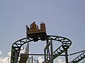
Spinning Racer

Spinning coasters , as seen in the picture above, are often a variant of the bogie design, which are schematically structured as follows:

The vertical axis of the spinning coaster around which the gondola with the seats rotates is not connected to one of the two chassis axes on a hinge, because the two chassis axes are both connected to a central part like a ball joint and are therefore symmetrical. So that the central beam with the gondola does not tip over, the central beam has two arms instead of the hinge, which form an additional horizontal axis. Movable trailers are attached to this, shown in purple in the drawing. These in turn rest on additional rollers on the axes. If the wagon moves into a torsion position, it is exactly in the middle of the two axles, i.e. not as inclined to the left as the front axle and not as inclined to the right as the rear axle, for example.
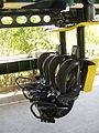
In the Crush's Coaster and Spinning Racer , the trailer has a trapezoidal shape and the different inclinations can be clearly seen on the Spinning Racer . In the introductory picture of the wheel suspension at the top , the additional wheel and the surface on which the trailer is lying can also be clearly seen. It is, unlike in the drawing, on the outside.
Steering knuckle
  |
In the Inverted Coasters , e.g. B. on the Wicked Twister , you can see the rotating wheel sets particularly well. They are as agile as a shopping trolley wheel. The seats and the frame are permanently connected to the axle on one side, in the two images above this is the right axle. On the other hand, the frame is connected to the next car with a ball joint, or to the single axle at the end of the train as shown above, which is now the left axle in the two pictures above. The Wicked Twister in full shot and other examples:

Wicked Twister

Velocity
Swamp thing

Jimmy Neutron's Atomic Flyer


The joint between the wagons can actually be a ball and socket joint as in the Swamp Thing or built with a cardan joint and axial bearing as in Jimmy Neutron's Atomic Flyer . The Wicked Twister takes as you can see the strong torsion good, but the roller coaster design tolerates close hilltops no narrow plane curves. In order to reduce the 'fluttering' of the steering, the wheel sets can also be connected by a rod in the trapezoid, as provided by the kingpin .
Individual evidence
- ↑ US Patent 1,319,888 (October 28, 1919) "John Miller Pleasure railway structure"
- ↑ Roller Coaster Steering , English discussion in the CoasterBuzz Forum, contribution by RideMan / Dave Althoff, Jr. from August 10, 2011, 6:34 PM. "If you are doing beam steering , as Arrow does, you have to rotate the entire axle to follow the curve."
- ↑ Roller Coaster Steering (as above). "In the Ackermann-style steering assembly used by Gravitykraft, the wheel carrier pivots relative to the axle (or in fact there doesn't even need to be an actual axle, but that's another issue)."
- ↑ To the steering trapezoidal pole: Seen on a picture of a 'motorcycle roller coaster' and on Gravity Group's test train - a closer look Holiday World & Splashin 'Safari, YouTube, published April 16, 2009, position 0: 50/1: 19.