
Signs for road fixtures

_Schieberschild.jpg)
Signs for supply facilities indicate (including street caps ) supply facilities and management organs such as underground hydrants or gate valves for water supply , sewage disposal, gas , district heating pipes, or their route.
Information signs for water pipes
Signs for fire hydrants
Hydrant signs point out hydrants , i.e. water extraction points from the water network. The size of the signs is 25 cm × 20 cm. Some water supply companies indicate the pressure and the amount of water that can be drawn for the fire service as additional information.
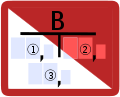
Systematics

| Area | description |
|---|---|
| 1 | Designation in the abbreviation of the built-in fitting. Usually an "H" stands for hydrant. Other abbreviations may stand for different special hydrants. |
| 2 | Inner diameter of the supply line in millimeters. As a rule of thumb, the inside diameter can be multiplied by 10 to estimate the possible extinguishing water withdrawal rate in liters per minute. |
| 3 | Distance between the shield and the hydrant from the shield to the left measured in meters and decimeters (right after the decimal point). |
| 4th | Distance between shield and hydrant from the shield to the right measured in meters and decimeters (right after the decimal point). |
| 5 | Distance between shield and hydrant from the shield just measured in meters and decimeters (right after the comma). |
| 6th | Component number for clear local allocation in a supply area (city or municipality). Not specified depending on the operator. |
Possible common abbreviations
- HR = hydrant is turned off clockwise and has turned anticlockwise be
- HL = hydrant is turned off anti-clockwise and will have turned right around to
- OH = above ground hydrant
- SH = shaft hydrant
- UH = underground hydrant
Examples of signs

Sign for an underground hydrant with a DN 300 line that is 1.1 meters to the left and 8.4 meters in front of this sign.

Sign for a post hydrant in Payerbach with the number 11 with a pressure of 8.6 bar; Flow rate of 1930 l / min and 0.6 meters in front of this sign.

Reference to a post hydrant and the operator

Blue hydrant sign to indicate that this technical hydrant can also be used for ventilation at z. B. high / low points is particularly suitable.

Sign for above and below ground hydrants in Frankfurt am Main

Red and blue hydrant sign on top of each other. The hydrant marked in blue is not intended for the extraction of extinguishing water. B. used for drinking water in a market .


Information signs for extinguishing water facilities

The signs indicate extinguishing water withdrawal points. A distinction is made between extinguishing water tanks (or cisterns) , extinguishing water wells with a built-in deep pump and extinguishing water wells for suction operation . The size of the signs is 25 cm × 20 cm.
Systematics

Extinguishing water well (DIN 4066 B1)

Extinguishing water cistern (DIN 4066 B2)
Extinguishing water well with integrated deep pump (DIN 4066 B3)
_mit_Legende.svg)

_mit_Legende.svg)
| Area | description |
|---|---|
| 1 | Distance between the shield and the tapping valve measured to the left of the shield . This is given in meters (field 3 and to the left of it) and decimeters (field on the right, after the comma). |
| 2 | Distance between shield and tapping valve measured to the right away from the shield . This is given in meters (field 4 and to the left of it) and decimeters (field on the right, after the comma). |
| 3 | Distance between shield and tapping valve measured straight away from the shield . This is given in meters (field 5 and to the left of it) and decimeters (field on the right, after the comma). |
| 4th | Water volume of the underground extinguishing water tank in cubic meters . |
Technical hydrants
In addition, there are so-called technical hydrants located on drinking or sewage pipes, which are used for maintenance purposes and not as fire extinguishing equipment, hydrant signs with a blue or green border and the following common symbols:
Common abbreviations
- BEV = aeration and ventilation valve
- SH = flush hydrant
- LH = ventilation hydrant
Information signs for water supply lines
Signs for water pipes indicate street caps (valve boxes) that give access to z. B. offer shut-off valves of the local water supply ( slide ).
Systematics


| Area | description |
|---|---|
| 1 | Designation in the abbreviation of the built-in fitting. |
| 2 | Inner diameter in millimeters of the supply line. |
| 3 | Distance between shield and built-in fitting measured away from the shield to the left . This is given in meters (field 3 and to the left of it) and decimeters (field on the right, after the comma). |
| 4th | Distance between shield and built-in fitting measured away from the shield to the right . This is given in meters (field 4 and to the left of it) and decimeters (field on the right, after the comma). |
| 5 | Distance between shield and built-in fitting measured straight away from the shield . This is given in meters (field 5 and to the left of it) and decimeters (field on the right, after the comma). |
Common abbreviations for built-in fittings in Germany
- ES = emptying slide. A line can be emptied with it. This takes place at the lowest point in the pipeline and usually in a receiving water (e.g. body of water), more rarely in a pump shaft.
- HS = hydrant valve. It is installed in front of a hydrant so that the hydrant can be disconnected from the network when changing.
- K / KL or AK = flap or butterfly valve.
- LS / LH or LV = ventilation slide, air tap or ventilation valve.
- MP = marker point. Marks the course of the line.
- PS = private slider.
- S = slide. With it, the connection between two lines can be separated or opened.
- SH = shaft. In an underground structure, for example, ventilation valves, water meters, pressure reducers or handwheels can be accommodated. The position of the manhole is marked with this board.
- SS = route pusher. In order to be able to shut off ( push out ) individual sections of the route if necessary on longer transport routes, section slides are installed at certain intervals.
- US = bypass valve. When closing a large-sized flap, this opens a passage around the flap for better sealing.
- ZS or TS = zone valve or separating valve. Zone sliders separate two zones from each other. They are of particular importance in locating leaks.
Information signs for water house connection pipes
(Water) house connection signs indicate the street cap (valve body) of a gate valve in the supply line that separates the installation in a building or property from the local water line. In most cases this is the last gate valve before the water meter. It is therefore important not to lower the street cap below surface level, so that, for example, in the event of a pipe break in front of the water meter shut-off fitting, the fittings behind it can be depressurized.
Systematics
Common abbreviations for built-in fittings
- A = connection
- AH = stopcock
- AS = connecting slide
- AV = connection valve
- HA = house connection
- VA = valve tapping

Description:
In this case, the name of the fitting is a connection valve. In this case, the nominal size of the pipe is not always given, the label "water" indicates a fitting in a water supply system. Otherwise, these signs are to be read in the same way as slide signs.
example

Description: This sign indicates a house connection valve that provides access to a gate valve of a house connection pipe. The in-street fitting is located 3 meters and 40 centimeters in front of this sign.
In some cases the entry of the house connection line into the building is marked from the outside by a blue point on the house wall.
Information signs for sewer pipes
Signs for sewer pipes indicate street caps or manhole structures that provide access to sewer fittings. Special sewage systems such as overpressure or underpressure systems are marked in this way, whereas ordinary sewer systems are rarely identified.
Systematics
Common abbreviations
For valves to shut off a house connection line:
- HA = house connection
- HK = House connection ball valve
- HP = house connection pipe plastic slider
- HS = house connection pipe slider
At main guides:
- ES = emptying slide
- K or KH = ball valve
- P or SP = plastic slider
- R = revision facility
- S = slide
example

Description: Wastewater information sign for a drainage valve
Information signs for gas pipes
Information signs for gas supply lines
General
Signs for gas pipes indicate z. B. street caps (valve boxes) that provide access to the shut-off valves of the natural gas network ( gate valve ), but also to pipe runs and other gas and associated electrical equipment. The difference to signs for transport lines is the 40 mm font size of the abbreviation and the mostly missing operator information. In terms of structure, signs for gas supply lines do not differ from those for water supply lines.
Common abbreviations for built-in fittings
- A or AB = blow out or blow off. It can be used to drain gas from the line. In contrast to the emptying slide , the AB has a separate slide usually labeled as an AS blow-off slide.
- AS and AK = gate valve or ball valve. They can be used to separate or open the connections between two lines.
- AT = shut-off pot.
- BL = shut-off bladder.
- HS and HK = main slide or main ball valve. With it, the connections between two lines can be separated or opened. In contrast to AS and AK , they are used to separate entire streets or districts.
- I or J = isolation point. Separates two measuring areas in the cathodic corrosion protection ( KKS ).
- K , KH or KU = ball valve. The abbreviation can vary depending on the provider.
- MK = measuring contact. measuring point in connection with the cathodic corrosion protection ( KKS ) one measures different potentials which are on the pipe.
- MP = measuring point. Measurement point of a route position
- OM = odor measurement point. Measuring point for the concentration of the added fragrance in the pipe network.
- RR = smelling tube. Pipe connections or protective tubes can be measured gas-free for a possible leak.
- WT = water pot. Any condensate that accumulates in the pipe is then drained off. Also for protective pipe drainage.
The following abbreviations can also be used:
- HD or H = high pressure
- MD or M = medium pressure
- LP or N = low pressure
As an example, a valve in the medium pressure network is given the abbreviation MS or SM . A ball valve in the low-pressure network NK or KN
Information signs for gas transport lines
General
In contrast to the signs for the supply networks, signs with 25 mm font size of the abbreviation are provided here. As a rule, an operator with a fault hotline is specified. The wording for the medium indicated on the label is "Ferngas" (formerly "Fern-Gas") or "Erdgas". Depending on the utility company, signs for transport lines are also used in the local network.
Common abbreviations of the signs
All common abbreviations for gas supply lines can be used for the abbreviations for transport lines. The following abbreviations are also listed here.
- BK = railway crossing (formerly RK for Reichsbahnkreuzung).
- D = stretcher. Prevents compression and strain in the pipe. Mostly in mining areas.
- FZ = flight sign. this marks the course of the route that is flown over for control.
- M or ZM = marker or an additional marker. They mark the location of a gas pipeline in the area.
- R = direction indication. Marks a significant change in the course of the route.
The following abbreviations can also be used:
- KZ = license plate
- L or LTG = line
- NR = number
Common abbreviations for equipment of telephone cables for gas transport lines
In the abbreviations for telephone cables, the first letter in the abbreviations is always the " K " for cable
- KA = branch socket
- KK = condenser sleeve
- KM = connecting sleeve
- KP = Pupin's coil
- KT = telephone socket
Systematics

Description:
| Area | description |
|---|---|
| 0 | Various information provided by the provider. Here is depending on the supplier z. B. the diameter, operating pressure or the part number specified. |
| 1 | Abbreviation of the valve. |
| 2 | Numbering of the valve or the inner diameter of the pipe. |
| 3 | Distance between the shield and the management body measured from the shield to the left . This is given in meters (field 3 and to the left of it) and decimeters (field on the right, after the comma). |
| 4th | Distance between the shield and the management body measured to the right away from the shield . This is given in meters (field 4 and to the left of it) and decimeters (field on the right, after the comma). |
| 5 | Distance between shield and management body measured straight away from the shield . This is given in meters (field 5 and to the left of it) and decimeters (field on the right, after the comma). With the "minus" sign, the fitting is behind the sign. |
| 6th | Specification of the operator with a telephone number for incidents. |
Examples

Description: This sign indicates a valve body that provides access to a main valve of a natural gas pipeline. The street fitting is 6.9 meters to the left and 3.1 meters in front of this sign.
Information signs for gas house connection lines
House connection fittings are also measured and signposted in the gas supply network. Here the structure does not differ from signs on house connection lines.
In most cases, the entry of the house connection line into the building is marked from the outside by a yellow dot on the house wall.
Common abbreviations for built-in fittings
- A = connection
- AS = connecting slide
- AV = connection valve
- GS = gas flow monitor
- HA = house connection
- VA = valve tapping
Information signs for district heating lines
General
These signs appear both as a pair of signs and as a stand-alone sign, since two pipes usually run parallel in district heating supply systems. The hot medium flows through the flow line from the heat generator to the consumer and the cooled medium flows back through the return line to the heat generator.
Installation fittings and manhole structures are specified here. Rarely also pipe runs.
Slider signs
Systematics

| Area | description |
|---|---|
| 0 | Various information provided by the provider. Here is depending on the supplier z. B. the diameter, operating pressure or the part number specified. |
| 1 | Abbreviation of the valve. |
| 2 | Numbering of the valve or the inner diameter of the pipe. |
| 3 | Distance between the shield and the management body measured from the shield to the left . This is given in meters (field 3 and to the left of it) and decimeters (field on the right, after the comma). |
| 4th | Distance between the shield and the management body measured to the right away from the shield . This is given in meters (field 4 and to the left of it) and decimeters (field on the right, after the comma). |
| 5 | Distance between shield and management body measured straight away from the shield . This is given in meters (field 5 and to the left of it) and decimeters (field on the right, after the comma). With the "minus" sign, the fitting is behind the plate. |
| 6th | Specification of the operator with a telephone number for incidents. |
Common abbreviations for built-in fittings
- E / ES = drain or drain slide
- HA = house connection
- L = ventilation
- S = slide
Possible abbreviations specified in field 0
- DN = inner diameter of the pipe
- PN = designed pressure level
example

Description: This pair of signs indicates two gate valves, one in the flow line and one in the return line. The sliders are located 1.5 meters to the left of the pair of signs. The flow and return lines are equipped with medium pipes with a nominal width of DN 80 and a nominal operating pressure of PN 16.
Information signs for electrical lines
General
These signs mark the route of underground high-voltage cables. In the past, such signs were also used for underground telephone cables.
Common abbreviations for built-in fittings
- K = cable
- C = condenser sleeve or condenser
- KM = cable sleeve
- P = cable pupin coil
- M = marker
- SR = protection tube
example

Sign of a protective tube with 150 mm inner diameter for a 20kv underground cable. The protective pipe is located 2.4 m in front of the shield under the earth's surface.
Information signs for pipelines

General
These signs are usually brown and attached to sign posts. They only mark the course of the line or a measuring point for cathodic corrosion protection .
In addition to abbreviations, plate numbers can also be specified here.
Road caps for fittings are not to be found here, as the slides are housed in fenced areas in the form of section slides.
Common abbreviations on the signs
- KM = line kilometers
- MK = measuring contact
- R = direction indication
Attachment

Signs are preferably attached to buildings and not to fences or posts because of their greater durability. If possible, a separate construction is set up on which the panels are attached. In Germany, according to current legislation, the owner of the property must tolerate the installation of signs on buildings, fences and walls within certain reasonable limits. If the signs are attached to specially built pillars, they are called sign posts, or at least in Austria markers .
Regional and company-specific differences
The abbreviations correspond to the signs in Austria , in other German-speaking countries they can vary slightly. It is also possible that different companies introduce additional terms or use different terms.
The format of signs is specified in DIN (building) standards, at least for Germany:
- DIN 4065 “Gas pipelines; Information signs "
- DIN 4066 "Information signs for the fire brigade "
- DIN 4067 “Water; Information signs, local water distribution and water pipelines "
- DIN 4068 “Wastewater; Information signs "
- DIN 4069 “Local gas distribution lines; Information signs "
- DIN 40019 "Signs for cable systems in the electricity supply"
There are corresponding standards for Austria (ÖNORM B 2526 "Information signs for gas pipes - design, use", in accordance with DIN 4065 and DIN 4069). For the letters, these standards refer to the sans serif font specified in DIN 1451 .
Marker (visual marker) / Austria

Markers, also known as visual markers, are used to identify underground pipelines in the area. They also serve to mark the position of the shafts and domes of shut-off devices. Signs are usually attached to the marker, which on the one hand precisely describe the dimensions and on the other hand the location of any fittings and shafts.
In Austria, the setting up of markers on pipelines in which certain dangerous goods are transported is regulated by law. These markers must e.g. B. lead the phone number of the operator.
Web links
- Website with information signs (especially for Germany)
- Stadtwerke Münster
Individual evidence
- ↑ DIN 4066
- ↑ ( page no longer available , search in web archives: without page title )
- ↑ cf. Grombach, P. et al (1993): Handbuch der Wasserversorgungsstechnik . S. 791. Munich: Oldenbourg Verlag.
- ↑ This is the description with bdb.at be found.
- ↑ Federal Law Gazette II No. 367/2005 : Ordinance of the Federal Minister for Economics and Labor on the measures to be carried out in borehole mining, Section 57 (1).
- ↑ Federal Ministry for Digitization and Business Location: Borehole Mining Ordinance § 56 (5); As of May 23, 2010