Workshop programming
The workshop programming , and workshop-oriented programming (WOP) ( English shop floor programming - SFP ) is a form of programming of CNC - machine tools at workshop level, dealing with simple data entry screens, dialog guidance and graphic display to the operator in the workshop directed. The name comes from the late 1970s. The terms dialog control and cycle control also describe this type of programming.
History of origin
With the introduction of the first CNC machine tools, program creation was shifted to work preparation . The skilled worker at the machine lost his job of converting a drawing into the machine's working movement. He only inserted workpieces and monitored the machine.
With the workshop-oriented programming, the skilled worker on the machine should be able to directly contribute his knowledge and experience. Because he is able to react much faster and more flexibly to malfunctions and problems than work preparation. He should be able to enter programs for simple parts directly on the machine and to be able to change difficult workpiece programs that were created in the work preparation on the machine and save them back again. For this purpose, the work preparation and workshop should use the same programming system for all machine types and technologies.
In order to generate an error-free program, the machining process should be simulated before processing with a mapping of the machine room, the tools and the clamping situation of the part.
The first machines with WOP control came onto the market in 1989.
aims
- Graphically interactive programming without an abstract programming language
- Programming of the workpiece geometry and not the tool paths, as with programming according to DIN 66025
- Program geometry independently of the processing technology
- Options for taking over geometry data from a CAD system
- Uniform dialogues for all manufacturing technologies
- Uniform programming in the workshop and in work preparation
realization
Various manufacturers offer industry or machine-specific WOP software for wood and plastics processing.
In metalworking , cycle-controlled machines meet most of the WOP's goals.
Some points of the WOP have been adopted into the software of the current CNC controls: z. B. Contour programming and graphic simulation.
To date (2015), no uniform and cross-technology WOP software has become established. The implementation is solved differently for each control manufacturer.
example
|
|||
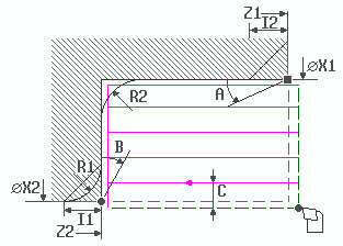
| Longitudinal machining cycle (extended) of the MANUALplus M control |
With this cycle of a lathe, a shoulder is turned from a diameter of X = 60 mm to a diameter of X1 = 40 mm. The shoulder has a radius R2 = 5 mm on the inside and a chamfer I1 = 1 mm on the left. Several cuts are made with the cutting depth C = 1.5 mm. The gray fields can optionally be filled out. If, for example, A = 1.5 is entered, a cone with 1.5 ° is produced.
Programmed in DIN:
N20 G0 X60 Z5 T1 G97 S800 (Anfahren)
N21 G0 X57 (Zustellen)
N22 G1 Z-20.4 G95 F0.3 (1. Schnitt)
N23 G0 X59 Z-19.4 (Abheben)
N24 G0 Z5 (Rückfahrt)
N25 G0 X54 (Zustellen)
…
While programming according to DIN 66025 / ISO 6983 requires that you enter all coordinates and functions yourself block by block, the dialog control relieves the user of much of this work. Here the operator selects the desired function and the control system asks for all the parameters required for processing and sometimes suggests different variants. This type of programming is also easy to learn.
The disadvantage, however, is that it is usually not possible to save information in a block that is only necessary later (e.g. calling up and prepositioning the tool changer for the next tool). When the operator is programming, the machine stands still and is not productive. However, since these controls are mostly used in single part and small series production, the advantages in terms of simplicity of programming outweigh the time lost in processing and programming.
Most of these controls offer the possibility to program any workpiece contour with interactive graphic support, which is then manufactured by the machine with the technology data entered. The control also calculates points of intersection, fillets, and chamfers as in a CAD program. Since approx. 1997 it has also been possible to read drawing data from an external CAD program as workpiece geometry directly on the machine. The data are usually transferred in the DXF file format . The control then creates the program together with the specifications of the skilled worker.
See also
Web links
Stefan Tomann: How to program today (PDF) ( Memento from October 27, 2005 in the Internet Archive ) DDS Edition 7/2003, at the Internet Archive
Individual evidence
- ↑ Uni Saarbrücken: Script for the practical experiment "Workshop-oriented programming", p. 9 (PDF) ( Memento from September 29, 2007 in the Internet Archive )
- ↑ without evidence, see discussion

