Ford and Fulkerson algorithm
The algorithm by Ford and Fulkerson is an algorithm from the mathematical branch of graph theory for determining a maximum flow in a flow network with rational capacities. It was named after its inventors LR Ford Jr. and DR Fulkerson . The number of operations required depends on the value of the maximum flow and is generally not restricted by polynomials . Further developments led to the algorithm by Edmonds and Karp and the algorithm by Dinic .
Working principle
The algorithm is based on the idea of finding a path from the source to the sink along which the flow can be increased further without violating the capacity constraints of the edges. Such a path is also known as an augmenting path . By repetition, the rivers along several such routes can be combined into an even larger total river. If the shortest path is always chosen, the Edmonds-Karp algorithm results .
So that the maximum flow can actually always be found in this way, it must also be allowed that the path follows edges of the network in the opposite direction and reduces the flow again for these edges (so-called rear edges, see below). In the analogy of a real liquid movement, for example through a pipeline network, this corresponds to the idea that instead of sending back part of the liquid flowing through a line, you can simply send a corresponding amount less through this line from the start.
Formal description
A network is given , consisting of a finite, directed graph with a source , a sink and a capacity function , which assigns a non-negative real number as capacity to each edge .
The algorithm changes an st flow in the network in each pass , i.e. a mapping with the properties
- Capacity restriction : for each edge the flow through is restricted.
-
Flow conservation : The following applies to every node :
- .
The number of edges leading out and the number of edges leading into it denotes here . The flow entering a node must therefore be the same as the flow leaving.
In each step the algorithm looks for a path from to in the residual graph . The residual graph shares the same set of nodes and contains the edges of that are not used by , supplemented by so-called back edges: for each edge with also contains a back edge . Formally, the following applies: This Residualkapazitäten be defined that each edge assign how much the river on can be increased yet, and each rear edge assign how much of the river on the associated Hinkante can be reduced. So formally:
Any flow can be used for initialization (including the zero flow, which assigns the value 0 to each edge ). The algorithm is described as follows:
- (Initialization with zero flow :) Set for each edge .
- As long as there is a path from to in the residual graph , find such a path and do:
- Determine .
- For all set: .
- For all set for the associated Hinkante : .
If all capacities are rational, the algorithm calculates a maximum st-flow after a finite number of steps.
example
| description | Graph (with capacities )
|
flow | Residual graph (with residual capacities )
|
||||||||||||||||||||||||||||||||||||||||||
| We consider the st-flow network , consisting of the graph with four nodes and five edges , the source , the sink and the capacity function given on the right .
We start with the empty flow that assigns the value to each edge . The residual graph thus corresponds exactly to the network and the associated residual capacities exactly to the capacities . |

|

|

|
||||||||||||||||||||||||||||||||||||||||||
| description | Augmenting path (with residual capacities )
|
flow | Residual graph (with residual capacities )
|
||||||||||||||||||||||||||||||||||||||||||
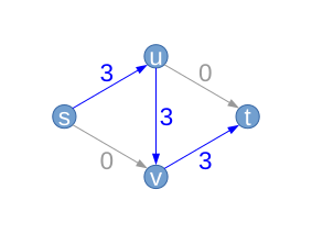
| Let us assume that the algorithm first chooses the path ; H. (blue). Along this path we can only increase the flow by at most (the middle edge from top to bottom). This results in a new flow (we refer to it again with ) with .
The edge has a capacity of , but we're only using it at the moment . In the residual graph, the edge is therefore retained with a residual capacity of . It is different, for example, with the edge where no residual capacity remains. It therefore "disappears" from the residual graph (shown in gray dashed lines). For the edge there is a residual capacity of . Furthermore, we now have three edges with a flow greater than zero. In theory, we can “send back” this flow, which is why we introduce three new “backward edges” whose residual capacity corresponds exactly to the current flow between the two nodes (red). |

|

|

|
||||||||||||||||||||||||||||||||||||||||||
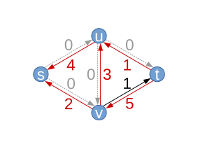
| Let's assume that the algorithm chooses the path in the next step . The maximum flow increase along this path results from the residual capacity of the edge . For the first time we use a rear edge, the edge . As the flow to f along the edges sv and ut is increased by 1, reduces the flow on the other hand along the edge uv by 1 from 3 to 2. Thus, the capacity of this edge exploited any longer, and the edge uv returns to the Residualgraphen back , this time with the residual capacity . Instead, this time ut "disappears" . The residual capacity of sv decreases by 1 to 1.
Note: all backward edges in the residual graph again have the same residual capacity, which corresponds to the value of the flow between their two nodes. |

|

|

|
||||||||||||||||||||||||||||||||||||||||||
| Next, find the algorithm e.g. B. again . This time the flow along this path can only be increased by 1, just the amount that we sent back along the edge uv in the previous step . You can already see here that the algorithm may shift a lot "back and forth", more on this under runtime . |

|

|

|
||||||||||||||||||||||||||||||||||||||||||
| In the last step, only the path can be found. This increases the flow again by 1, for a total value of the flow of . This can also be seen from the fact that the edges starting from the source s together have a flow of , as do the edges ending in the sink t . This flow is actually maximal, which can easily be seen from the fact that all edges emanating from the source are fully utilized (these two edges are a bottleneck, i.e. the cutting edges of a minimal cut ).
The algorithm then terminates because no path from s to t can be found in the resulting residual graph . If the algorithm were to be supplemented to the extent that it investigated which nodes of s can still be reached, the above-mentioned minimum cut would result automatically, in this case it only contains the node s , from which no other can be reached (see Max-Flow -Min-Cut Theorem ). |

|

|

|
correctness
Ford and Fulkerson were able to prove that an st-flow in a network is maximal if and only if there is no augmenting path, i.e. i.e., if the remaining network has no path from to . Therefore:
- If the Ford and Fulkerson algorithm comes to a standstill, a maximum st-flow is found.
The maximum st flow does not have to be clearly determined.
When executing the algorithm, the considered flow increases with each step. From this follows an important fact for integer networks:
- If all capacities of the given network are nonnegative integers, then the algorithm of Ford and Fulkerson comes to a standstill after a finite number of steps and delivers a maximum st-flow which is also an integer.
If all capacities are rational numbers , then one obtains an integer network by multiplying it with the main denominator and can thus prove the following statement:
- If all capacities of the given network are nonnegative rational numbers, then the algorithm of Ford and Fulkerson comes to a standstill after a finite number of steps and delivers a maximum st-flow which moreover only has rational values.
If irrational numbers occur as capacities, this no longer applies: Ford and Fulkerson constructed an example of a network with 10 nodes and 48 edges, in which their algorithm does not stop with a suitable selection of the augmenting paths and also does not converge to a maximum flow. In 1995 Uri Zwick found an example with 6 nodes and 8 edges and such behavior.
running time
The algorithm by Ford and Fulkerson finds a maximum flow in calculation steps (see Landau notation ), where the number of nodes in the network, the number of edges in the network, the value of the maximum flow and the main denominator of the capacities denote.
On the one hand, each loop pass of the algorithm only requires operations, but on the other hand the required number of loop passes depends on the size of the capacities. It is possible to choose the paths that enlarge the river very unfavorably. This can be illustrated by the example on the left: In this example, the algorithm can choose a path over the middle edge (possibly as a back edge) in this example and thereby only increase the total flow by 1.
If one always chooses a shortest augmenting path for increasing the flow in each step , one obtains the algorithm of Edmonds and Karp , which always constructs a maximum st flow in running time . The Dinic algorithm brings a further improvement with the help of additional techniques with a (worst-case) complexity of .
Pseudocode
 1 Eingabe: Ursprungsgraph
 2 Ausgabe: Graph mit maximalem Fluss
 3
 4 Berechne Restgraph aus Ursprungsgraph
 5 Solange es einen Erweiterungspfad im Restgraph gibt:
 6 	Restkapazität = Minimum( Restkapazität der Kante für jede Kante des Erweiterungspfades )
 7 	Für jede Kante des Erweiterungspfades:
 8 		Falls Kante in Ursprungsgraph:
 9 			Fluss( Kante ) = Fluss( Kante ) + Restkapazität
10 		Sonst:
11 			Fluss( umgekehrte Kante ) = Fluss( umgekehrte Kante ) - Restkapazität
literature
- Bernhard Korte , Jens Vygen : Combinatorial Optimization: Theory and Algorithms . Translated from the English by Rabe von Randow. Springer-Verlag, Berlin Heidelberg 2008, ISBN 978-3-540-76918-7
Web links
- An annotated source code in C ( Memento from June 25, 2005 in the Internet Archive ) (English)
- Web applet in Java - testing the Ford and Fulkerson algorithm on your own graph
Individual evidence
- ^ LR Ford Jr., DR Fulkerson: Maximum flow through a network . In: Canad. J. Math. . 8, 1956, pp. 399-404. doi : 10.4153 / CJM-1956-045-5 .
- ^ Lester Randolph Ford Jr., Delbert Ray Fulkerson: Flows in Networks, Princeton University Press 1962
- ↑ Uri Zwick: The smallest networks on which the Ford-Fulkerson maximum flow procedure may fail to terminate , Theoretical Computer Science 148, 165-170 (1995).


