
Amphibious bridge and transfer vehicle M2

The amphibious bridge and transfer vehicle M2 “Alligator” (called “amphibian” for short in everyday parlance) was a pioneering device of the German armed forces, which was also used by the armed forces in Great Britain and Singapore .
After the available bridge and translation device had turned out to be very cumbersome to use when the Bundeswehr was deployed, demands were made on the industry to remedy the situation. They wanted to set up a kind of rapid reaction force in order to be able to carry out crossings over wider bodies of water with the help of highly mobile bridge equipment as flexibly as possible. The decision was made in favor of the M2 amphibious vehicle developed by Eisenwerke Kaiserslautern (today General Dynamics Land Systems ) since 1958. The M1 version presented by the rival consortium MAN / Krupp had been rejected because of serious technical problems.
A total of 235 vehicles were manufactured, of which the Bundeswehr received a total of 114 copies in the years 1967–1970. Of these, 36 units were assigned to one of the three amphibious engineer battalions of the corps (AmphPiBtl 130 in Minden, AmphPiBtl 230 in Ingolstadt and AmphPiBtl 330 in Speyer). The individual battalions thus had a capacity of 183 m floating bridge with the military load class (MLC) 60 (54.4 t load capacity), which was sufficient to accommodate the M48 bridge-laying tank , which was the heaviest vehicle in the Bundeswehr at the time.
The last vehicles went to the main system overhaul in 1982. By 1996 it was retired and replaced by the amphibian M3 .
Possible applications
In addition to the (theoretically) endlessly extendable floating bridge, ferry operations could also be carried out. In this case there were three options: the single ferry (carrying capacity 8 t), the double ferry (carrying capacity 25 t) and the triple ferry (carrying capacity 60 t). Depending on the space requirements, the double and triple ferry was closely or widely coupled - i.e. H. between the two vehicles (or between the two outer and the central vehicle) the ramp bodies were inserted (wide) or left out (narrow). To operate the multiple ferry, the authority of command was transferred from the vehicle driver to a ferry driver. Thus, twelve single ferries, or six double ferries or four triple ferries could be operated per company. In floating bridge operation, the company was able to bridge 63 meters. Use without anchoring was only possible up to a flow velocity of 3 m / s. The maximum load was MLC 60.
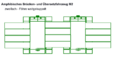
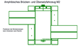
Use with additional ramp sections

Single ferry

Double ferry - closely coupled
Double ferry - widely coupled
Triple ferry - closely coupled

Triple ferry - widely coupled

Bridge arrangement. Right vehicle with access ramp


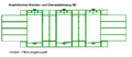
Use without additional ramp sections
Position of the bridge ramps when building a ferry or bridge. Dock to the right

Ferry service three times as far
Ferry service triple tight
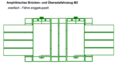
Ferry service twice as tight

Ferry service twice as far


The additional ramp parts required were tracked on trailers.
technical description
It was an aluminum construction vehicle, consisting of a main float and two side floats that were half as wide. When driving on the road, these were folded up and upside down on the main floating body. The folding movement took place via hydraulic cylinders and a joint. A rudder propeller was located under the steering position of the main float , which took over the main drive and control of the vehicle on the water. In addition, each side float was equipped with a smaller and more rigid propeller. These two were powered by the second motor. After the side floats had reached the end position after being swiveled out, they were each locked with two bolts; these bolts reached through the holes of two tabs that were inserted into recesses in the main float. At the same time, the power connection from the gearbox to the two propellers was established via toothed segments.

A mechanical crane for positioning the ramp parts was attached in front of the water operator's steering position. The crane arm was 7.2 m long, the max. Load was 600 kg.
The vehicle had a fire extinguishing system and hydraulic level control.
The ramps (four per vehicle) were lifted out of their bearings with the crane and turned by 90 degrees to the side edge of the main floating body fastened with bolts (hinge system). The ramps were arranged as required; four positions were possible on each side. A hydraulic cylinder in the side float was located under each ramp section, with which the ramps could be raised and lowered.
One motor drove the rudder propeller, the other the two side propellers. Both could be operated independently, but the vehicle could not be steered without a rudder propeller. The two drive shafts for the side propellers each ran via a ship's reversing gear that could be switched electrically from forward to reverse.
The doors to the driver's cab could be closed watertight. There were two emergency exit hatches in the roof (thus on the floor of the steering position). The communication between the land driver and the water operator (both positions were only occupied at the same time when entering and exiting water) took place via a mouthpiece.
Only one of the two engines was used when driving on the road. (Both could be coupled to the drive shaft, but not at the same time.) As a rule, which motor was used depended on the number of operating hours reached.
In the main float there were two bilge pumps, one in the genset room and one in the driver's cab. The side floats were not equipped with bilge pumps, as they were not necessary to lift the unloaded vehicle. The main float was sufficient to keep the vehicle afloat and maneuverable even when the side floats were full.
business
Four soldiers were required to operate the vehicle:
- a non-commissioned officer or senior corporal as a driver and water operator (BBS and class C driving license required)
- a corporal or senior corporal as a driver and crane operator
- two soldiers as helpers
Due to the awkward dimensions of the vehicle, only experienced drivers could be used when driving on the road. The excess width, the spongy driving style, the high seating position and the poor view through the small side windows made the highest demands on the driver, especially on country roads. The vehicle rocked a lot off-road.
To travel on the water, some modifications had to be made. The vehicle was set up with the driver's cab facing the water. Then the side floats were unfolded and locked, the baffles erected and the extensions of the exhaust pipes pulled out. If there was enough space, the bridge ramps could be set ashore on command. After the vehicle lost grounding, the land driver disengaged and retracted the wheels. He then left the cab and operated the crane and the levers of the ramp hydraulics. Before the actual job could begin, the water operator first had to turn the vehicle in the desired direction.
The speed at which the boat was driven on the water was not fixed and in practice was dependent on the prevailing outside temperature. The warmer it was, the faster it was driven to allow the water driver standing on the driver's cab to cool off.
To drive several vehicles together to form a widely coupled ferry or to build a floating bridge, the approaching vehicle set the two ramps to the rear on the side to be coupled and diagonally forward on the other side. It then approached the last vehicle in the row, if possible standing still in the current, at an angle from behind until the appropriate position was reached. Then the ramps were lowered by the two land drivers and bolted by the helpers.
After setting the ramps, the crane arm was unlocked in the middle and folded in horizontally. He was then turned to the right and locked in that position.
With skilful use of the rudder propeller and auxiliary propeller, inclined travel, sideways travel and turning on the spot were easily possible.
Leaving the water was carried out with the stern first (on the road side and seen from the land driver). To do this, the rural driver brought the wheels back into the road driving position, put the vehicle in reverse and waited until the vehicle had touched the ground before driving the amphibian ashore. However, since he could not see where he was going during this procedure, he had to rely on the commandant's instructions. This informed him of the corresponding course corrections through the mouthpiece.


Technical specifications
| M2 and M2B | |
|---|---|
| Manufacturer | EWK / KHD |
| Useful life | 1967-1996 |
| Weight | 21,500 kg (MLC 23) |
| length | 11.3 m |
| width | 2.99 m |
| height | 3.58 m |
| Ground clearance | 200-840 mm |
| engine | 2 × KHD F8L714A multi-fuel - each 130.9 kW at 2300 rpm |
| transmission | ZF S-6-55 |
| Power take-off | ZF Z-65 |
| Width with side float unfolded | 5.87 m |
| Width with set ramps | 14.16 m |
| wheelbase | 5.35 m |
| Front track | 2.13 m |
| Rear track | 2.16 m |
| Speed on land max | 60 km / h |
| Speed on the water max | 15 km / h |
| Fuel supply | 500 liters |
Remarks
- ↑ The vehicle belonged to the AmphPiBtl 330 in Speyer. At the time of the admission it was in the Kurpfalz barracks there.
- ↑ As the rudder propeller was used during normal water travel, the left motor driving it reached a higher number of operating hours over time. To compensate for this, it was often switched to the right engine on land.
- ↑ The driver's cab had no connection to the engine room behind it.
- ↑ It was a non-commissioned officer position
- ↑ at that time the highest rank of the team
- ↑ Operating license
- ↑ It was a main corporal position
- ↑ So actually with the stern first when driving in water
- ↑ Unfolding the side floats on the water was practically possible, but prohibited.
literature
- Technical regulations of the Bundeswehr “Amphibious Bridge and Transfer Vehicle M2” Part 12 and Part 22
- Central service regulation of the Bundeswehr 33/320 (rapid floating bridges)
- Training and teaching material "Amphibious bridge and transfer vehicle M2" operating license
Web links
- Bundeswehr Classix: bridge and translation vehicle (1967) ( YouTube video of the Bundeswehr)
- Bundeswehr Classix: Amphibious Pioneer Companies of the Bundeswehr - Building a Bridge over the Danube (1973) (YouTube video of the Bundeswehr)
- M2 on panzerbaer.de