Turbo compressor

The turbo compressor (also turbo compressor ) is one of the thermal turbo machines. It works in the reverse of the principle of the turbine .
construction
All turbo compressors own
- a housing with appropriate control devices
- a wave with at least one
- Impeller with blades or a row of blades drawn directly onto the shaft.
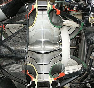
Turbo compressors are divided into the main types radial and axial compressors . With an axial compressor, the gas to be compressed flows through the compressor in a direction parallel to the shaft. With a radial compressor, the gas flows axially into the impeller of the compressor stage and is then deflected outwards (radially). With multistage centrifugal compressors, a flow deflection is therefore necessary after each stage. In general, axial compressors deliver higher volume flows while radial compressors generate higher pressures. Combined designs suck in large volume flows with their group of axial stages, which are then compressed to high pressures in the subsequent radial stages. The diagonal compressors are a combination of both principles.
In the frequently built single-shaft machines that u. U. are also driven via a separate gear, the individual compressor stages are arranged one behind the other on the shaft. The arrangement is often such that there is one main direction of flow (from the suction to the discharge nozzle), sometimes a "back to back" arrangement of individual compressor stages or groups of stages is selected to compensate for the axial thrust of the shaft, so that there is more than one suction - or pressure connection results.
Gear compressors are another design, in which the individual radial compressor stages are grouped directly around a gear housing. This gear has a central large (toothed) wheel which drives several parallel pinion shafts, each carrying one or two running wheels. The large wheel is either directly coupled to the prime mover (motor drive) or, in turn, is driven by a drive pinion (turbine drive) that is usually located below.
Each group of stages can run at its optimum speed depending on the diameter. Gear compressors achieve very high pressure ratios of up to around 70.
application
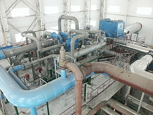
Turbo compressors are used when large gas volume flows are to be compressed. B.
- in gas turbines and jet engines
- as a blast furnace and steel mill fan
- in systems for air or gas liquefaction
- as an air or nitrous gas compressor in nitric acid systems
- in petrochemical plants and refineries
- for increasing pressure in gas pipelines
- as a vacuum blower in the paper industry
business
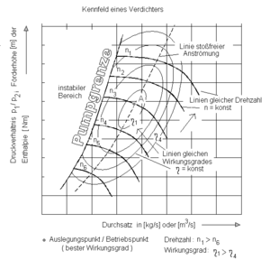
An operating point is set at the intersection of the pressure loss characteristic of the downstream system components with the respective compressor characteristic. The special properties of the gas medium to be conveyed must be taken into account here: When pressure is applied, the volume decreases and the temperature increases at the same time.
Prime mover
The output of large turbo compressors is between one megawatt and around 60 MW. The choice of drive machine is significantly influenced by the application. If there is sufficient and safe steam available - as in chemical plants, steelworks or ironworks - a steam turbine is preferred . Gas turbines are ideal for pipeline and offshore applications. Often, the drive is also provided by an electric motor, which can also be operated with a variable speed via a frequency converter . To utilize “superfluous” pressure at the end of chemical processes, hot gas expanders are used, which can be viewed as a special form of turbine .
Power regulation
To adjust the compressor output, either the speed of the drive machine or the volume flow of the compressor can be regulated. With electric motors, speed control is usually implemented using a frequency converter . The speed of the turbine drive can also be varied within certain limits.
Adjustable guide vanes (axial compressor) or adjustable inlet guide vanes (radial compressor) are usually used for volume flow control.
The regulation via suction throttle valves is considered out of date due to excessive energy losses.
Combined controls (speed and volume flow control) are possible, but are avoided if possible.
Compressor pumps
One of the typical properties of every turbo compressor is the tendency to “surge” in unfavorable operating conditions - a phenomenon that occurs when a certain pressure falls below a minimum mass flow. The flow to the compressor blades depends on this. If the mass flow is too small, the angle of attack becomes so large that the flow breaks off . This means that less momentum is transmitted to the medium, so that the mass flow continues to decrease and the flow also breaks off at other blades or compressor stages. The pressure difference between the outlet and the inlet cannot be maintained, there is a backflow through the compressor. The pressure ratio decreases (suction pressure increases) and the compressor delivers again until the pumping point (falling below the minimum delivery rate) is reached again. This process runs cyclically with a frequency of approx. 0.3–5 Hz and is associated with a typical noise.
Pumping occurs at different intensities depending on the severity of the compressor mismatch. If there is a slight mismatch, a "rotating stall" occurs, with only individual blades of the compressor experiencing a stall. The flow stall rotates against the direction of rotation of the compressor. This is associated with a growling or humming noise and leads to a slight decrease in the performance of the compressor. The compressor blades are already excited to vibrate, which can lead to blade breakage. If the mismatch becomes larger, it can come to a total stall, with the performance totally collapsing and a loud bang. If the compressor belongs to a more modern aircraft engine, it is usually associated with destruction of the engine.
Practically all turbo compressors therefore have surge limit control , which is intended to prevent the flow rate falling below a certain minimum. This minimum volume flow is to be understood as the respective pressure-dependent setpoint of the surge limit control and in turn forms the control line for anti-surge, which runs in the characteristic map about 10% to the right of the surge limit. When crossing this control line, the volume flow is increased again by opening a relief valve (especially air compressors) or bypass valve (other gases), so that the operating point is at least kept on the control line.
If a longer recirculation operation is to be expected, a recirculation cooler is required, as otherwise the gas drawn in would become increasingly warmer, which in turn favors the pumping of the compressor due to the decreasing density.
Axial compressors in particular react very sensitively to pump surges and must therefore be particularly protected against this operating state. They often have additional, independent devices for anti-surge protection that protect the machine from destruction if the surge limit control fails (failure of measuring or control equipment, changed gas composition).
Blowing off or recirculating the compressor dramatically worsens the efficiency of the compressor, since a partial flow of the gas is uselessly conveyed back to the suction nozzle or into the atmosphere. This is why this process is not used for power control, but primarily serves to protect the machine. If a machine can only be operated with a partially open anti-pump valve under normal process conditions, the machine is not optimally adapted to the process or has to be overhauled (contamination / wear of the blades and diffusers).
In Linz ( Austria ) around 1980, ground vibrations at around 1 Hz were measured and the cause was found in compressors used in industrial ammonia pressure synthesis, where remedial action was taken.
Intercooling
The compression in the compressor is polytropic in real cases and leads to an increase in temperature according to the pressure ratio; the cooling of the compressor is beneficial because the compressor work required is smaller. The cooling can possibly also take place beyond the isentropic course and theoretically cool the volume flow so much that the compression is almost isothermal. However, this requires many intermediate cooling processes.
Technically, this is often implemented using external intercoolers, especially in gear compressors that already have connecting pipelines between the individual stages. In addition, compact designs are common, in which the coolers are integrated into the compressor housing in pairs between the stages.


