Bandpass subsampling
Under bandpass subsampling means the sub-scan of a continuous band-limited signal at a sampling frequency which is smaller than and the Nyquist-Shannon sampling theorem is not fulfilled. By carefully selecting the sampling frequency, the continuous signal in the bandpass position can be restored in the baseband without loss of information .
The process of bandpass subsampling can also be referred to as digital mixing and is used in the digital down converter . The advantages are a lower sampling rate , cheaper analog-to-digital converter and less data volume. A disadvantage is the effort for the absolutely necessary and eponymous analog bandpass filter .
Application example
In order to receive FM radio stations between 88 MHz and 108 MHz, the sampling frequency after passing through an anti-aliasing filter (low pass at 108 MHz) would have to be at least , i.e. at least 216 MHz. If you remove all frequency components below 88 MHz and above 108 MHz from the analog signal that are not of interest by means of a bandpass, the analog signal can be digitized completely and loss-free with a bandwidth of 20 MHz with a sampling frequency of slightly more than 40 MHz.
Calculation of the possible sampling frequencies
Calculation of m max
f min : lowest frequency of interest
f max : highest frequency of interest
B : bandwidth of the frequency band of interest
trunc: round off, cut off
Seen clearly, the number m max says how often the desired spectrum between 0 Hz and the lowest interesting frequency f min has "space".
Choice of m
In order to be able to calculate possible sampling frequencies, m ( m ≤ m max ) must now be selected or a table must be created for all m .
Please note the following when choosing m :
- m is straight: The signal is to be found in the normal position after scanning. That is, the lowest frequency in the analog signal also gives the lowest frequency in the sampled signal.
- m is odd: the signal can be found in an inverted position after scanning. That is, the lowest frequency in the analog signal gives the highest frequency in the sampled signal.
- The larger m , the lower the resulting sampling frequency.
- The larger m , the more precise the sampling frequency must be.
Calculation of the possible sampling frequencies
f smin : minimum sampling frequency
f smax : maximum sampling frequency
Calculation for the example of FM radio
| m | f smin | f smax | comment |
|---|---|---|---|
| 0 | 216 MHz | ∞ | Standard situation, Nyquist frequency |
| 1 | 108 MHz | 176 MHz | Upside down |
| 2 | 72 MHz | 88 MHz | Standard situation |
| 3 | 54 MHz | 58.67 MHz | Upside down |
| 4th | 43.2 MHz | 44 MHz | Standard situation |
If the inverted signal is desired ( m must be odd) and m = 3 has been selected (highest possible odd m for lowest sampling frequency), the sampling frequency can be between 54 MHz and 58.67 MHz without any information being lost.
If the signal is required in the normal position ( m must be straight) and m = 4 has been selected (highest possible even m for the lowest sampling frequency), the sampling frequency can be between 43.2 MHz and 44 MHz without any information being lost.
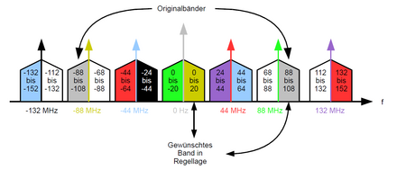
Graphic illustration in the spectrum
For the graphic representation, the original spectrum must be shifted with ± f s ( sample frequency ) and its harmonics.
Calculation:
- f s ± f min and f s ± f max
- -f s ± f min and -f s ± f max
- 2f s ± f min and 2f s ± f max
- -2f s ± f min and -2f s ± f max
- etc.
Graph for m = 3
Concrete calculation for the positive fundamental oscillation of the sampling frequency (selected: f s = 55 MHz; red in the figure):
Calculation of the upper band
- 55 MHz + 88 MHz = 143 MHz
- 55 MHz + 108 MHz = 163 MHz
Calculation of the lower band
- 55 MHz - 88 MHz = -33 MHz
- 55 MHz - 108 MHz = -53 MHz
Graph for m = 4
Concrete calculation for the positive fundamental oscillation of the sampling frequency (selected: f s = 44 MHz; red in the figure):
Calculation of the upper band
- 44 MHz + 88 MHz = 132 MHz
- 44 MHz + 108 MHz = 152 MHz
Calculation of the lower band
- 44 MHz - 88 MHz = -44 MHz
- 44 MHz - 108 MHz = -64 MHz
When digitizing, a so-called sample-and-hold element must be used, which has a readout interval that is as narrow as is required for sampling at 2 · f max (in the specific example, 216 MHz).
literature
- Arthur Kohlenberg: Exact interpolation of band-limited functions . 1953.


