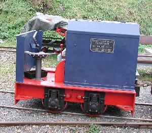
Diema DL 6
| Diema DL 6 | |
|---|---|
|
Diema DL 6 with Deutz engine
|
|
| Number: | 220 |
| Manufacturer: | The MA |
| Year of construction (s): | 1955-1970 |
| Axis formula : | B. |
| Gauge : | 500, 600, 700 mm u. a. |
| Length over buffers: | 1,650-1,790 mm |
| Width: | 1,000 mm |
| Fixed wheelbase: | 500 mm |
| Service mass: | 1–1.15 t |
| Wheel set mass : | approx. 0.5 t |
| Top speed: | 8 km / h |
| Continuous output : | 4-6.2 kW |
| Motor type: | Single cylinder diesel engine |
| Power transmission: | mechanically |
The DL 6 from Diepholzer Maschinenfabrik Fritz Schöttler (Diema) is a diesel locomotive for light railways . With a weight of around 1 t, a length of around 1.7 m and an axle base of 0.5 m, it is one of the smallest locomotives ever.
History and versions
The DL 6 was created in 1955 as a smaller and less powerful version of the DL 8 . A total of 220 copies were built, making the DL 6 one of the most successful Diema designs. The locomotives were mainly used by small peat extraction companies. The last locomotive was delivered in September 1970; the successor model was the outwardly almost identical DFL 10 .
18 machines deviated from the standard, including tunnel designs called DL 6 T and DL 6/3 T. The variant DL 6/3 or DL 6/3 T built from 1968 onwards differed from the standard version in that it had a newer and slightly more powerful engine.
technology
The locomotives are built on a welded outer frame. The width of the frame depended on the gauge , in particular there was a version for the 700 mm gauge, which was widespread in the Netherlands. The models from 1957 onwards have a frame that is about 10 cm longer. The "buffers" consist of a bent piece of sheet steel.
Air-cooled single-cylinder diesel engines between 4 and 6.2 kW are used in the DL 6, initially from Güldner and later from Deutz . The Güldner variant (33 pieces) could be recognized by a slightly lower engine cover. Many of the Güldner engines were later replaced by the more reliable Deutz engines, so that today there are hardly any examples with Güldner engines.
The power is transmitted via a V-belt from the engine to a mechanical two-speed transmission and from there via roller chains to the two axles. These were initially supported by evolution springs ; later coil springs were installed.
The first copies had a brake acting on the gearbox and optionally a shoe brake acting on only one axis. The gear brake was later omitted and both axles were braked, initially using a lever with notches, and finally using a throw lever.
As is usual with locomotives of this category, the driver's seat is installed across the direction of travel so that the driver does not have to change his position when changing direction. The engine, gearbox and gear lever are located to the right of the driver and the brake lever to the left. Some locomotives have a roof resting on four supports; At least one DL 6/3 also has the cab end walls with window openings.
