Displacement mapping
View-dependent displacement mapping (VDM) describes a technique in computer graphics that is used to give a surface of a three-dimensional object a higher level of detail and thus to achieve a more realistic representation.
Basics
3D objects in computer graphics initially consist of a grid or polygons , over which a so-called texture (for example a picture of a wall) is later placed. One can imagine texturing, i.e. the application of a texture, as if its surface were glued onto the wire frame model of an object to be represented. In addition to the actual texture data, which usually contain the final color design of the surface, other types of texture data (which describe the surface structure, for example) are sometimes referred to as "texture".
application
A so-called - is, together with the actual texture of the object - usually from this height-map (narrow for height map. Relief ) is generated. This is an image that mostly uses grayscale to indicate elevation information. From these, a cross section through the surface to be created and thus a relief can be generated.
The points of the grid ( vertices ) are shifted according to this texture information along their normal , i.e. perpendicular to the surface. For example, it is possible to transfer a height relief to a flat ( planar ) surface by applying a displacement map and thus to give it a rough structure. In addition to shifting, it may be necessary to refine it, depending on the density of the wire mesh. One then speaks of tessellation .
example
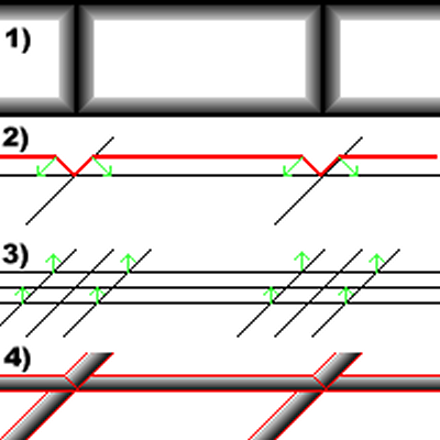
In the example, a wall is to be given a surface using displacement mapping, on which each individual brick protrudes slightly in relation to the joint. A corresponding texture is used as a template (Figure 1). This is used to create the height map (Figure 2).
- The height information of the surface is obtained from the height map and
- projected onto the surface. It becomes necessary to refine the grid of the surface in order to be able to represent the new structure.
- The points (vertices) of the new grid are shifted along their normals by the distance specified in the height information.
- The resulting three-dimensional structure reproduces the projecting bricks on the planar surface as desired.
Advantages over other methods
In contrast to normal mapping and bump mapping , displacement mapping has the advantage that the geometry of the object is actually changed. This means that if you look at a surface from close up at a flat angle, its structure still remains visible. In contrast, according to other methods, the surfaces appear absolutely planar as soon as they are viewed from a steep angle. In addition, the effects that simulate a structure through mere color changes are lost. Structures created with displacement mapping appear more realistic under the influence of light sources and shadows, since the changed geometry also affects the lighting (for example, when a surface is viewed from a flat angle and casts shadows).
Web links
- Demo applet (requires corresponding hardware support for the graphics card) (offline)


