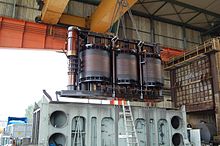
Three phase alternating current transformer
A three-phase AC transformer , three-phase transformer or three-phase transformer combines the three individual transformers required for transformation in a three-phase system into a single one. Typically, power transformers are designed as three-phase transformers. The first three-phase transformer was built by Michail Dolivo-Dobrowolski at AEG in Berlin in 1890 , after he had previously developed the three-phase system there. The first practical use of three-phase transformers for the electrical transmission of energy with highly transformed three-phase alternating current took place the following year at the three-phase transmission Lauffen – Frankfurt as part of the International Electrotechnical Exhibition in 1891 .
construction
Three-phase transformers are constructed similarly to single-phase transformers . In contrast to these, however, the primary and secondary sides each consist of three separate windings - usually labeled U, V, W for the high-voltage side and u, v, w for the low-voltage side - which are mounted on a soft magnetic iron core , which is usually a "closed E “Resembles, are housed (see adjacent sketch). The three parts of the core wound with the coils are called legs , the iron core bridge over the three legs is called the yoke . In the simplest, most common case, the high and low voltage winding of each phase is attached to the same leg, separated by insulation material and, in later use with large transformers, also oil. But there are also five-limb cores (see below). The cores are composed of textured sheet metal with a thickness of 0.35 mm, for example, so that the magnetic flux runs in the direction of the texture as far as possible.
For the conceptual derivation of the overall structure, one starts with three single-phase transformers for one phase each - each with a winding and a closed core. The unwound leg, the return leg, serves to close the magnetic circuit . Now imagine the three transformers joined together in a star shape on the return leg, so that a common return leg is created for all three transformers. With a symmetrically loaded three-phase system, i. H. With the same load on all three outer conductors , the magnetic fluxes cancel each other out in the common return leg of the iron core due to the phase shift , which is why the return leg can be omitted. Thus, as shown in the sketch, the core can be designed as a three-leg core.
However, the symmetrical case cannot always be ensured during operation; one then speaks of an unbalanced load , which in some vector groups leads to an undesirable neutral point shift and a strong magnetic leakage flux . To avoid this condition, some three-phase transformers, depending on the vector group (e.g. coupling transformers in the vector group "Yy0"), are either provided with a five-leg core with two additional outer return legs or, in the case of three-leg core design, with an additional tertiary winding for compensation. Such a compensating winding is connected in delta and only carries a (ring) current when the load is unbalanced. It ensures the stability (symmetry) of the star point when the load is unbalanced. One of the main windings can also take over this function for the other main winding connected in star if it is connected in delta.
How the total of six connections per side of a three-phase transformer are interconnected is determined by the vector group . The usual connections are star and delta connections , which in principle can be combined as required on both sides. This results in different phase shifts between the external conductor voltages on the high and low voltage side, which cannot be just 0 ° or 180 ° as in single-phase transformers. In these cases the transmission ratio is expressed by a complex factor that also includes the phase shift. For this reason, the vector group must be observed when operating several three-phase transformers in parallel.
example
The vector group Dyn5 of a three-phase AC transformer means:
- D = high voltage winding in delta connection
- y = undervoltage winding in star connection
- n = brought out star point (neutral conductor)
- 5 = phase shift between high and low voltage is: 5 * 30 ° = 150 °
Restrictions

For very high voltages and large transmission capacities, it is not possible to build three-phase alternating current transformers that can be transported on public roads. Therefore, three single-phase units are normally used.
literature
- Gregor D. Häberle, Heinz O. Häberle: Transformers and electrical machines in power engineering systems . 2nd Edition. Europa-Lehrmittel, Haan-Gruiten 1990, ISBN 3-8085-5002-3 .
- Gerd Fehmel, Horst Flachmann, Otto Mai: The master's examination in electrical machines . 12th edition. Vogel Buchverlag, Oldenburg / Würzburg 2000, ISBN 3-8023-1795-5 .
Web links
- Schematic drawing , ASA Trafobau
Individual evidence
- ↑ Michael von Dolivo-Dobrowolsky and the three-phase current ( Memento of the original from October 24, 2010 in the Internet Archive ) Info: The archive link was inserted automatically and has not yet been checked. Please check the original and archive link according to the instructions and then remove this notice. , VDE website.
- ^ Gerhard Neidhöfer: Michael von Dolivo-Dobrowolsky and the three-phase current. Beginnings of modern drive technology and power supply. VDE book series history of electrical engineering. Volume 9, 2nd edition. VDE Verlag, Berlin / Offenbach, ISBN 978-3-8007-3115-2 .
- ↑ Dolivo-Dobrowolski ( memento from July 23, 2012 in the web archive archive.today ), WEKA Media Lexicon.
- ↑ http://antriebstechnik.fh-stralsund.de/1024x768/Dokumentenframe/Versuchsanleitungen/EMA/Trafo.pdf BR Oswald: Lecture Electrical Energy Supply I Script Transformers (Corrected Edition 2005) , teaching material from the University of Hanover / Institute for Energy Supply and High Voltage Technology, accessed on Feb. 6, 2019


