Felixstowe F series
| Felixstowe F series | |
|---|---|
|
|
| Type: | Flying boat |
| Design country: | |
| Manufacturer: |
Production was distributed among many companies in the UK |
| First flight: |
1915 |
| Commissioning: |
1916 |
| Number of pieces: |
F.1: 1 |
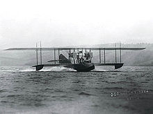
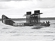
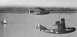
The Felixstowe F-series was a series of biplane - flying boats whose hull in the British Seaplane Experimental Station of the Royal Naval Air Service in Felixstowe constructed and numerous subcontractors and the built by Curtiss structures combined. Curtiss himself incorporated some versions of the F series into his own product line. The Royal Naval Air Service (RNAS) and the later Royal Air Force (RAF) put the machines in the First World War in the North Sea and the Mediterranean as a naval reconnaissance one. A precise reconstruction of the development history of the F-series is only inadequately possible in some aspects, as the information in the literature varies greatly.
history
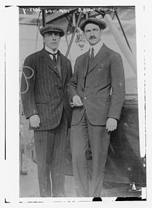
In April 1914, the British pilot and designer John Cyril Porte left England to join Glenn Curtiss in the USA and work with him on a project to cross the Atlantic . For this purpose, a newly constructed flying boat (Curtiss H-1) called America should be used. The H-1 used two Curtiss OX-5 engines with only 90 hp each and would probably not have been able to take off from the water with the intended take-off weight for an Atlantic crossing.
Curtiss H-4 as a starting point
When the First World War broke out, Porte returned to England, where he was given command of the RNAS (Royal Naval Air Station) Felixstowe in September 1915. On the basis of his experiences at Curtiss, he recommended that the independent Royal Naval Air Service (RNAS) , which emerged from the Naval Wing of the Royal Flying Corps on July 1, 1914, purchase flying boats from this manufacturer. In October and November 1914, the first two H-4 flying boats based on the H-1 reached Felixstowe (serial numbers 950 and 951). In March 1915, four more H-4 flying boats were already in service with the RNAS (1236 to 1239). 56 more copies of the H-4 were then ordered from Curtiss and eight machines were built in England by the Aircraft Manufacturing Company (Airco). In use, however, the weak points turned out to be too weak a fuselage shell with poor hydrodynamic properties and the unreliable Curtiss engines. Porte and his team with the chief engineer JD Rennie therefore carried out a large number of tests with the hull in 1915 and 1916, primarily to improve the seaworthiness and service life of the aircraft.
F.1
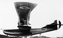
This work led to the F.1, the first version of the Felixstowe flying boat series. In the assembled only in one copy F.1 the structure of the Curtiss H-4 (serial number 3580 was after Air joint Numbering System Committee (1912 to 1916) ) with the single-stage, 10.98 m long Porte-boat hull Porte I combined. Porte further increased performance on the water with a second and later also a third boat step and a more pointed V-shape in the lower area of the hull cross-section. The F.1 stayed in Felixstowe until 1919, where it was used for seaplane training.
F.2 / F.2A
The RNAS probably received the first built copy of the Curtiss H-8 in March 1916, which was an enlarged version of the H-4. A subsequent test showed similar problems as with the H-1 and H-4 with regard to the weak structure of the boat hull and the inadequate performance of the Curtiss engines, which with 160 hp each were unable to pull the fully loaded machine out of the Raise water. The H-8 was therefore equipped with two more powerful Rolls-Royce engines with an output of 250 hp . Although the machine was now able to take off without any problems, the hydrodynamic properties had deteriorated significantly. Porte therefore decided to build a completely new hull, similar to that of the F.1. This resulted in the only F.2 that used the H-8's structure. The new, 12.81 m long hull was named Porte II and had a sharper keel and two boat steps. It was designed and built in the spring and early summer of 1916 and probably in July 1916 and adapted to the structure of the Curtiss aircraft. The hull proved to be more resilient, had better seaworthiness without increasing the weight. The F.2 was used for reconnaissance over the North Sea; it was lost on September 30, 1916 east of the steep coast of Naze.
In 1916, the RNAS also received the first of 60 ordered Curtiss H-12A flying boats that were delivered without engines. Since the boat hulls were exposed to heavy wear, it was not uncommon practice to replace the original H-12 hull with an F.2A hull, sometimes after less than a year of use.
Series production of the F.2 as F.2A then followed at the Aircraft Manufacturing Company in Hendon , at SE Saunders , May, Harden & May and also in the USA at Curtiss and the Naval Aircraft Factory (NAF). Curtiss referred to the pattern as H-16 (according to other sources as H-12 or H-12A) and at the NAF it carried the Navy designation PN . Six other companies in Great Britain built the boat hulls alone. The F.2A used two 360 hp Rolls-Royce Eagle VIIIs. The armament consisted of one or two Lewis machine guns in the bow, one in a defensive stand on the back of the fuselage, one on each side of the fuselage and optionally one on the left side of the Cockpits . The offensive armament included two 230 lb (104 kg) bombs under the wings. The maximum take-off mass was 5000 kg and the maximum speed was over 150 km / h. The cockpit was initially partially covered, but was open again in the later construction lots. The maximum flight time was typically six hours and could be increased to up to 9½ hours by carrying additional petrol cans. By March 1918, 161 machines had been ordered and at the end of the war the RAF had 53 F.2A and 69 H-16s in their inventory. A total of 173 F.2A and 75 H-16 (H-12?) Were delivered.
Two copies of the F.2C variant were built (experimental serial numbers N64 and N65). These had a lighter, modified hull and two Eagle VIII engines. Both machines were in use in the summer of 1917.
The first F.2A were used to combat submarines from Great Yarmouth in February 1918 . On June 4, 1918, the biggest conflict between seaplanes during the entire war took place when four F.2a, one H-12 and 14 German float planes fought off the islands of Terschelling and Ameland . Three Hansa Brandenburg aircraft were shot down and two F.2A were significantly damaged, but were able to return to the base. Each F.2A was then given an individual, brightly colored coat of paint with unusual geometric patterns in order to increase the visibility after a ditching and to be able to distinguish the aircraft from the air. The aircraft stationed in Great Yarmouth were given checkerboard , stripes and zigzag patterns to suit the personal taste of the crew. Felixstowe planes used a more standardized scheme based on variations of stripes and squares.
F.3
The F.3 was slightly larger than the F.2A, but otherwise very similar. Although the F.3 was built in larger numbers, it was inferior to the F.2A in some properties. The F.3 was slower and less manoeuvrable, but could carry a larger bomb load and had a greater range. The armament typically consisted of four to five Lewis machine guns and four 230 lb (104 kg) bombs. The prototype of the F.3 was created in October 1917 by converting the first F.2C (N64). a. two 320 HP Sunbeam Cossack engines were installed. A number of F.3's intended for anti-submarine combat in the Mediterranean were built in Malta. The first Maltese F.3 (N4310) was tested in March 1918. By the time the armistice was reached, at least 30 other machines had been manufactured there. At that time, a total of 96 F.3s were still in service with the RAF.
F.5
The last variant of the F-series was the F.5, the prototype (N90) of which was tested in Felixstowe in November 1917. The F.5 also had the Eagle VII and Eagle VIII engines, but compared to the F.3 it had a deeper fuselage. She kept the two keel steps and an open cockpit with seats next to each other. At least four Lewis machine guns and four 230 lb bombs could be carried. Since the F.3 was still in series production, the Ministry of Munitions wanted to avoid the production of additional construction devices, so that the series F.5 were produced using many F.3 components. However, the F.5 received a fully timber-planked hull, while the F.3 and its predecessors were still covered with fabric in the upper area and the rear side parts. The curb weight increased accordingly from 3613 kg to 4130 kg, making the F.5 a little slower than its predecessor. The performance in the water and in the air was rated as very satisfactory. However, it was no longer used in the First World War.
British manufacturers of the F.5 were Gosport Aviation Company , Aircraft Manufacturing Company , May, Harden & May , Phoenix Dynamo Manufacturing Company , SE Saunders and Short Brothers. Even before the armistice, overseas production at Canadian Airplanes Ltd. in Toronto and at the US Naval Aircraft Factory.
The US Navy decided to introduce the F.5 on a large scale as the F.5L (from 1922: PN-5). The F.5L had two 12-cylinder Liberty engines with an output of 330 hp. Deliveries began on July 30, 1918. A total of 227 F.5L were built for the Navy, 137 of them at the Naval Aircraft Factory, 60 at Curtiss and 30 at Canadian Aeroplanes Ltd. The F.5L remained in service with the US Navy until 1931.
Technical specifications
Data to London, p. 260 f.
| Parameter | F.1 | F.2A | F.2C | F.3 | F.5 |
|---|---|---|---|---|---|
| crew | at least 4 | ||||
| length | 11.95 m | 14.11 m | 14.03 m | 15.00 m | 15.02 m |
| span | 21.96 m | 29.17 m | 28.98 m | 31.11 m | 31.62 m |
| height | 5.34 m | 5.49 m | 5.51 m | ||
| Wing area | 78.2 m² (?) | 105.26 m² | 105.53 m² | 133.03 m² | 130.90 m² |
| Empty mass | 3427 kg | 3081 kg | 3613 kg | 4130 kg F.5L: 3746 kg |
|
| Takeoff mass | 4984 kg | 4650 kg | 5550 kg | 5760 kg F.5L: 5900 kg |
|
| Top speed | 153 km / h | 152 km / h | 146 km / h | 141 km / h | |
| Service ceiling | 2900 m | 3140 m | 2440 m | 2070 m | |
| Flight duration | 6 to 9 h | 6 h | 6 to 9 h | 7 h F.5L: 10 h |
|
| Engines | two Anzani , 100 PS (74 kW) two Hispano-Suiza , 150 PS (110 kW) |
two Rolls-Royce Eagle VIII , 360 PS (265 kW) | two Rolls-Royce Eagle VIII (N64), 360 PS (265 kW) two Rolls-Royce Eagle VII (N65), 322 PS (237 kW) two Sunbeam-Coatalen Cossack (N65), 250 PS (184 kW) |
two Rolls-Royce Eagle VIII, 360 PS (265 kW) two Rolls-Royce Eagle VII, 322 PS (237 kW) |
two Rolls-Royce Eagle VII, 322 PS (237 kW) two Rolls-Royce Eagle VIII, 360 PS (265 kW) two Liberty 12 (Canadian F.5L), 400 PS (294 kW) |
| Armament | - | four to nine 0.303 Lewis machine guns two 230 lb bombs |
two 0.303 Lewis machine guns four 230 lb bombs |
four or five Lewis MG four 230 lb bombs |
four 0.303 Lewis MG four 230 lb bombs |
literature
- Peter London: British Flying Boats. Sutton Publishing, 2003, ISBN 0-7509-2695-3 .
- JM Bruce: The Felixstowe flying boats Part 1. In: Airplane Monthly October 1982, pp. 536-541.
- JM Bruce: The Felixstowe flying boats Part 2. In: Airplane Monthly November 1982, pp. 622-625.
- Jack Meadows: Diary of a North Sea Patroller - Naval Air Service flying-boat pilot Cecil Clayton Part 1. In: Airplane Monthly August 1997, pp. 46-51.
- Jack Meadows: Diary of a North Sea Patroller - Naval Air Service flying-boat pilot Cecil Clayton Part 2. In: Airplane Monthly September 1997, pp. 54-60.
- ER Johnson: American Flying Boats and Amphibious Aircraft. McFarland and Co., 2009, ISBN 978-0-7864-6269-8 .
- Peter M. Bowers : Curtiss Aircraft 1907-1947. Putnam, 1979, ISBN 0-370-10029-8 .
Web links
- Naval Aircraft Factory and F.5L (PDF; 1.1 MB)
- Smithsonian Institute Felixstowe F.5L
- Canadian Felixstowe F.3
- Earlyaviators John Cyrill Porte
Individual evidence
- ^ Air Committee Joint Numbering System (1912 to 1916)
- ↑ Curtiss Aircraft 1907-1947, p. 90
- ↑ London p. 18
- ↑ London, p. 24
- ^ Curtiss Aircraft 1907-1947, p. 92
- ^ Meadows, Airplane Monthly September 1997, p. 59
- ^ Johnson, American Flying Boats, p. 41
- ^ Curtiss Aircraft 1907-1947, p. 92
- ↑ London, p. 25
- ↑ London, p. 29
- ↑ London, p. 35
- ↑ Description and many drawings of the paint samples in Cross and Cockade Vol. 21 No. 4 1990 (p. 22)

