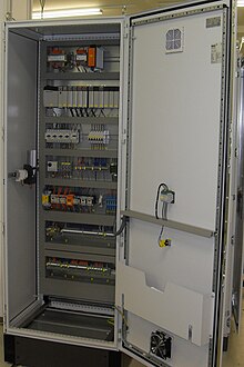
Filter fan
Filter fans consist of a combination of a fan ( fan ) and a dust filter ( air filter ). They are used to cool housings with electronic components, in particular to cool switch cabinets . In the case of higher demands on cleanliness inside the control cabinet and use at high ambient temperatures and contaminated ambient air, cooling units are used instead of filter fans, in which no air exchange takes place between the inside of the control cabinet and the environment.
functionality
Filter fans are used when the passive control cabinet cooling is not sufficient to maintain the desired internal temperature. The prerequisite for their use is that the switch cabinet environment is relatively clean and that the ambient temperature is below the desired internal cabinet temperature. The cool ambient air is sucked in by the fan, cleaned via a filter mat and fed into the interior of the housing. The air absorbs the heat from the components installed in the cabinet, heats up and then exits the cabinet via an outlet opening.
Cooling with a filter fan reaches its limits if either the amount of heat to be dissipated is too high, the ambient temperature is not sufficiently below the internal temperature, or if the degree of protection does not allow openings in the control cabinet.
properties
- The filter fans are offered as standard in the protection classes (according to IEC 60529) IP 43 or IP 54. The higher protection class IP 55 is achieved through the use of folded filter mats; IP 56 is achieved with a special hose-proof hood and fine filter mat.
- The filter fans can be equipped with a temperature control to reduce fan noise. If the ambient temperature is low or if there is little heat development in the cabinet, the fan speed is then reduced.
- The air performance of the fans is typically between 20 m 3 / h to 700 m 3 / h.
- Filter fans are typically used in the control cabinet with power losses between a few hundred watts and a few kilowatts.
- EMC shielding (see Electromagnetic Compatibility ) is possible and is implemented using a metallic layer on the filter fan housing and a special sealing frame.
- Thanks to a clip mechanism, the filter fan can be quickly installed without a screw connection, and the dust filter can be easily changed.
Installation blowing or suction
In most cases, the filter fans are installed in such a way that they blow the outside air into the control cabinet. This creates overpressure in the control cabinet and prevents unfiltered ambient air from entering.
The filter fans can also be installed upside down so that they suck the warm air out of the switch cabinet. A negative pressure then arises in the cabinet and unfiltered 'false air' can be sucked in through leaks.
Control cabinets are often also equipped with a so-called roof fan (so called because it is integrated in the roof of the control cabinet). The roof fan sucks the warm exhaust air out of the switch cabinet and releases it to the environment. The roof fans are usually not filter fans. The dust filter is located separately from the fan in an air inlet opening in the lower part of the cabinet.
Dimensioning
The required volume flow of a filter fan depends on the power loss of the components built into the housing and on the difference between the maximum permissible indoor and outdoor temperature. The calculation is based on the following formula:
- : Volume flow (in m 3 / s)
- : specific heat capacity of the air (in J / kg * K)
- : Air density (in kg / m 3 )
- : installed total power loss (in watts)
- : maximum permissible internal housing temperature (in ° C)
- : maximum permissible ambient temperature (in ° C)
example 1
- : 500 W
- : 40 ° C
- : 20 ° C
Example 2
- : 500 W
- : 40 ° C
- : 30 ° C
Dimensioning via air constant
The following applies to the simplified calculation of the air volume flow:
- : Volume flow (in m 3 / s)
- : Air constant (in m 3 K / Wh)
- : installed total power loss (in watts)
- : maximum permissible internal housing temperature (in ° C)
- : maximum permissible ambient temperature (in ° C)
The required volume flow can also be achieved by combining several filter fans.
| Height above sea level [m] | Air constant [m 3 K / Wh] |
|---|---|
| 0 to 100 | 3.1 |
| 100 to 250 | 3.2 |
| 250 to 500 | 3.3 |
| 500 to 750 | 3.4 |
| 750 to 1000 | 3.5 |
| 1000 to 1250 | 3.6 |
| 1250 to 1500 | 3.8 |
| 1500 to 2000 | 4.1 |
example 1
Height: 80 m above sea level
- : 500 W
- : 40 ° C
- : 30 ° C
Example 2
Altitude: 1580 m above sea level
- : 500 W
- : 40 ° C
- : 30 ° C
maintenance
The filter mat in the filter fan is dirty and must be replaced regularly.
See also
literature
- Klingenberg, Gottfried: Control cabinet and housing air conditioning in practice, Part II . Mählin Werbung Düsseldorf, 1996, ISBN 3-923270-07-0
- Styppa, Heinrich: Air conditioning for housings, machines and systems . Verlag modern industry, 2005 (The Library of Technology, Volume 284), ISBN 3-937889-28-0
Web links
- Dimensioning of filter fans (PDF file; 305 kB)
- Rittal manual: System air conditioning , Chapter : System air conditioning technology, pages 68 to 71 (PDF file; 41.81 MB)
- Schroff filter fan


