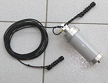
Long wire antenna
A long wire antenna was originally understood to be an end-fed antenna conductor whose length was greater than λ. In the amateur radio sector, an end-fed antenna whose length is in the λ ⁄ 2 range is generally referred to as a long-wire antenna.
This design is preferably used in the shortwave range . By definition, a long-wire antenna is at least as long as half the wavelength. For the 160 m band , which corresponds to a wavelength λ = 160 m, a long wire antenna is 80 m long.
Long wire as a receiving antenna
Long-wire antennas are particularly interesting for reception if they are several wavelengths long. They then have a clearer directional effect along the span direction, which can also be made asymmetrical with a suitable terminating resistor to earth ( beverage antenna ).
Shorter long-wire antennas have hardly any advantages on the receiving side compared to much shorter antenna variants, because in the shortwave range the receiver sensitivity is limited by the atmospheric noise and not by the noise of the receiver. For receiving purposes, preference should therefore be given to antennas that are as far away from sources of interference as possible and that also have a sensible directional characteristic. This can be done in the reception area e.g. B. can be achieved quite easily with compact magnetic antennas .
Long wire as a transmitting antenna
Long-wire antennas have typical dimensions of λ / 2 up to a few multiples of the wavelength for transmission. With longer antennas, the efficiency drops, the effort no longer brings any advantages, and the directional diagram also has numerous minima. The above-mentioned directional effect cannot therefore be used on the transmission side. In practice, such a transmitting antenna is only several wavelengths long if it is designed for a lower band (such as, for example, 80 m band 40 m long), but e.g. B. is operated at 20 m (2 wavelengths). If possible, such a long wire antenna is supplemented by another one for the correspondingly higher bands. In the former Soviet Union, some radio stations use long-wire antennas, known as Zarya antennas . Long-wire antennas are also occasionally used for medium-wave transmitters that are operated at a location with a grounded antenna carrier, for example a location that is primarily used for VHF and TV supply. In these cases the wire length is usually in the order of λ / 4 to λ / 2, sometimes shorter than λ / 4.
Fuchs antenna and similar designs
Long-wire antennas that are exactly λ / 2 or λ or 3/2 λ or more multiples thereof are high-resistance at the end and have a wave impedance of about 2000 Ω and above. They are therefore supplied with voltage; high voltages with minimal currents occur at the feed point. Long wire antennas require a resonance transformer to adapt to the considerably lower impedance of conventional coaxial cables of 50 Ω. Traditionally, a parallel resonant circuit ("fox circle") is used for this. This design is called "Fuchs antenna" after Josef Fuchs , radio amateur from Austria, who patented this antenna design in 1927.
Alternatively, instead of the parallel resonant circuit, a balun with a corresponding transmission ratio of z. B. 1: 9 can be used, whereby the long wire can be used for multiple bands without tuning the adapter.
Another alternative to feeding the long wire is the Zeppelin antenna. A ribbon cable with a length of λ / 4 is used for impedance matching . The ribbon cable serves not only as an impedance transformer, but also as a counterweight, so that a Zeppelin antenna can be operated similar to a symmetrical antenna without grounding. The name of this antenna design comes from the first application in the 1920s on airships like the Zeppelin . The impedance transformation through the ribbon cable corresponds to:
with the wave impedance of the ribbon cable, for example 450 Ω. This means that the impedance of a coaxial cable with Z in = 50 Ω can be matched to the impedance of the long wire antenna of approx. 4 kΩ.
The big advantage of the fox antenna and related designs are:
- in the case of reception, the preselection by the voting group,
- when transmitting the significantly increased bandwidth of around 10% of the center frequency,
- the high-resistance supply reduces the supply current.
- The earthing system, which significantly influences the antenna efficiency with low-resistance fed, asymmetrical antennas, is no longer decisive.
With many ground plane antennas , the typical design of asymmetrical, low-resistance fed antennas, the grounding system consists of up to several hundred wires when used in the medium wave range, each one quarter of the wavelength long.
literature
- Ulrich Freyer: Antenna technology for radio practitioners . 1st edition. Franzis-Verlag, 2000, ISBN 3-7723-4693-6 .
- Alois Krischke: Rothammels Antennenbuch . 13th edition. DARC-Verlag, 2013, ISBN 978-3-88692-065-5 .
Individual evidence
- ^ Josef Fuchs: Tests on a method of voltage feeding the antenna . QST, July 1928, p. 37, 42 .
- ↑ Patent DE225204 : Air duct structure for airships. Registered on September 19, 1909 , inventor: Dr. Hans Beggerow.
- ↑ Zepp end-fed antennas. Retrieved January 5, 2015 .


