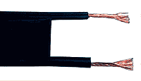
Ribbon cable
A two-wire line , even ribbon cable , English twin lead , or rarely parallel wire and twin line called, is a in the characteristic impedance defined, two-pole electrical line which in the field of high-frequency technology is used for balanced transmission of high frequency signals. The usual use of these lines is the electrical connection of symmetrical antennas in the frequency range from a few kHz to a few 100 MHz.
Depending on the specific embodiment, various other terms are common for this type of line. If the two-wire line is designed as an open two-wire line with spacers, it is colloquially and among radio amateurs also known as " chicken ladder " and sold under this name through specialist dealers. The half-open ribbon cable , English window line , is characterized by regularly arranged openings in the insulation material between the two conductors.
construction
In this line, the two electrical conductors are at a characteristic distance from one another, which among other things determines the line impedance of the line, and are kept at this characteristic distance by spacers or a plastic sheath along the line. The two-wire line is one of several types of the so-called Lecher line .
In contrast to the symmetrical cables used in the field of data transmission, the distances between the conductors are designed with closer tolerances, there is no twisting , and the conductors are arranged at a greater spatial distance to achieve a high line impedance.
application
In the middle of the 20th century, ribbon cables were used in tube receivers and the first television receivers to connect the receiving device to the antenna, as the symmetrical receiving antenna can be connected without impedance matching and the attenuation of the received signal is lower than with the coaxial cables commonly used today . The disadvantage of the ribbon cable is, since the HF energy is transmitted in the area between the two conductors, a higher susceptibility to interference and only a low shielding attenuation - several flat ribbon cables that are run in parallel have strong and mostly undesirable couplings. When routing a two-wire line, for example, make sure that there are no metallic objects next to the two-wire line.
The conversion of the antenna signals to the coaxial cables, which later became common on receiving devices, and their coaxial connectors are carried out by means of so-called baluns .
Further applications are in the area of amateur radio stations for connecting symmetrical antennas. The two-wire line can also consist of only two conductors, which are fixed at regular intervals by spacers. The primary dielectric then represents the air between the conductors.
Ribbon cables can be connected directly to the following antennas, among others:
- Dipole antennas , in particular λ / 2 dipoles with symmetrical feed such as the folded dipole
- Yagi-Uda antenna
- Butterfly antenna
- Rhombus antenna
parameter
The line impedance of a ribbon cable, as shown in the adjacent sketch, is:
with the relative permittivity , which represents a material constant of the insulation material used between the conductors, and 120 Ω as the wave resistance of the vacuum divided by the number of circles .
The usual line wave resistances of two-wire lines are 600 Ω, 450 Ω, 300 Ω and 75 Ω. In particular, the ribbon cable with 300 Ω was a common value in early radio and the first television receivers, which in newer receivers with a coaxial antenna connection can be converted to the 75 Ω common for coaxial cables using a balun with impedance matching of factor 4. The line impedance is selected at 185 Ω for the higher power of transmitter systems, since there the losses are lower.
With the given insulation material, the two-wire line has the following optimal line wave resistance:
- Smallest attenuation at a / d ≈ 2.276 with Z = 175.6 Ω
- Greatest dielectric strength at a / d ≈ 2.932 with Z = 208.6 Ω
- Largest power transfer at a / d ≈ 2.146 with Z = 167.7 Ω
literature
- Otto Zinke , Heinrich Brunswig: High Frequency Technology 1 . 5th edition. Springer, 1995, ISBN 978-3-540-58070-6 .
Individual evidence
- ↑ a b Karl Rothammel, Alois Krischke: Rothammels Antennenbuch . 13th edition. DARC Verlag, 2014, ISBN 978-3-88692-065-5 , Chapter 5.5: Two-wire cables.
- ↑ The Chicken Ladder Dipole . Retrieved April 28, 2018.
- ↑ Product for building such lines: Chicken ladder spreader . Retrieved April 29, 2018.


