
Lecher line
The Lecher line , or the Lecher system , is an arrangement named after the Austrian physicist Ernst Lecher (1856–1926) and consists of a two-wire line for resonance studies and as impedance matching for high-frequency electrical signals.
construction


A Lecher line of its original type consists of two parallel wires of a certain length, which are either open at their ends or connected to one another. Standing waves are formed along this line section according to the feeding frequency. If there is sufficient high-frequency power at the fed end, it is possible to detect current bulges with incandescent lamps and voltage bulges with glow lamps .
For adjustment purposes or to determine an unknown wavelength or frequency, there may be a short-circuit slide on the line .
Lecher lines can be used as a bandpass or bandstop filter - the distributed capacitance of the line and its inductance form an oscillating circuit. A Lecher line can also be understood as a mismatched , finite line, at the closed or open end of which reflection takes place.
Circuits made up of symmetrical or asymmetrical line sections are called line circuits . At high frequencies, in addition to waveguide arrangements, they are an alternative to resonant circuits and filters made from discrete components. See also stripline .
Special lengths

Voltage curve with short circuit on the left and free end on the right

Voltage curve in the event of a short circuit on both sides
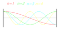
Stress curve with free ends on both sides


As soon as the line length for alternating current exceeds about 5 percent of the wavelength, even short pieces of wire must not be viewed simply as electrical connections, but as a string of very small (infinitesimal) inductances, at whose connection points small capacities can store charge ( line coating ). The calculation must be carried out with the help of line theory and the sometimes surprising results lead to often strange constructions, especially with devices in the radar area. The transforming properties of special lengths are of particular importance. Such arrangements can also be constructed as a cup circle or strip conductor. If the lines are adjacent to an insulating substrate, as in a "printed circuit", its shortening factor must be taken into account.
λ / 2 line
A line, the length of which corresponds to exactly half the wavelength λ of the feeding frequency, does not transform , but “transfers” the impedance - regardless of its characteristic impedance - from one point to another. This does not change if it is extended by further λ / 2 pieces.
- If one end is "open" and therefore has a very high impedance, this can also be measured at the other end. A half-wave dipole shows exactly this property .
- If one end is connected to "ground" (in printed circuits this is the copper surface on the back), the other end also has very low impedance, which is also known as series resonance or a virtual short circuit. In general, a line of this length always produces the same impedance at the end that is present at the other end.
λ / 4 line
An open line with the length of an odd multiple of a quarter of the wavelength λ is used when the impedance is to be greatly changed.
- If one end is connected to ground directly or via a low-inductance capacitor, a particularly high impedance is measured at the other end; the line acts like a parallel resonant circuit and insulates particularly well at this frequency . A λ / 4 line is an ideal choke with a negligible DC resistance.
- If one end is open, the other acts like a virtual zero point with a lower impedance than a capacitor, however good it is.
Applications of the λ / 4 line

The door seal of a microwave oven, for example, is a λ / 4 line: Since the built-in magnetron transmits at a wavelength of 12 cm, the gap is exactly 3 cm deep. The inner edge facing the magnetron acts like a short circuit for 2.45 GHz and prevents the emission of high-frequency energy.
Another application shows the detailed picture of the amplifier part of a low-noise signal converter ( LNB ). The signal is picked up by the antenna on the left edge of the picture, amplified in three stages and then passes through a band filter before its frequency is reduced to around 2 GHz by a mixer diode (bottom right outside the picture). In the picture you can see some λ / 4-long, wide conductor tracks, the starting points of which are marked with a red X. There they act as virtual ground points and replace blocking capacitors against ground. The distance between a collector and the emitter of the following transistor has the length λ / 2.
Closed coaxial or waveguide arrangements with a short-circuit slide moved by a micrometer are used to measure wavelengths and frequencies in the decimeter and centimeter range (see wave meter ).
The acoustic analogue of the standing electromagnetic wave in the Lecher line are Kundt's dust figures . Bass reflex housings are the analogue of the open λ / 4 line: At the resonance frequency of the bass reflex box, the deflection of the loudspeaker membrane is low, while the maximum oscillation amplitude prevails at the end of the bass reflex tube ("open end").
Electrotechnical description
The capacitance per unit length of a Lecher line with the conductor diameter and the distance between the conductor centers is


- .

The inductance coating is


and thus the line impedance , neglecting the discharge coating and the resistance coating:

or in simplified form:

with the relative permittivity ε r of the insulating material.
literature
- Otto zince , Heinrich Brunswig: high frequency technology. Volume 1: High Frequency Filters, Lines, Antennas , 5th, revised edition, edited by Anton Vlcek, Hans Ludwig Hartnagel. Springer, Berlin a. a. 1995, ISBN 3-540-58070-0