Butterfly antenna
The term butterfly antenna is used in the German-speaking world for several different antenna designs, all of which resemble the open wings of a butterfly.
Butterfly dipole
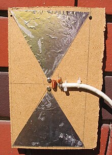
This dipole antenna is a flat dipole and is also called a spreading dipole. You can think of this antenna as a wire antenna with end capacities or as a double wire fan. The design as a surface reduces the losses and simplifies the construction. The electrical length is λ / 2 (half-wave dipole) at the lower frequency limit and at least λ (full-wave dipole) at the upper limit. Due to the spread angle, the feed point impedance becomes steady at this and also at a further increasing frequency (angle principle). The bandwidth of these antennas, which are particularly common for UHF reception, is practically about 2: 1 and thus covers the entire IV / V frequency band .
This antenna got the name butterfly dipole from the translation of the English name butterfly antenna . It is a linear antenna for broadband applications and in spite of the planar formation of the dipole it is not a planar antenna .
Batwing dipole
Another wing-shaped antenna is the batwing antenna . The feature is the slot between the two surfaces connected to one another at the ends. Thus this antenna is already one of the area antennas.
The function of the batwing dipole can be explained by imagining two λ / 4 lines short-circuited at the ends at the feeding points of a spreading dipole . The areas of the expansion dipole are then enlarged up to the line ends. Like the λ / 4 lines, the slot that forms is in resonance (see also slot antenna ). The other slots in the surface improve the current distribution and the frequency behavior. The compact surface can be replaced by a grid construction, the corners can be rounded - this creates the typical appearance of bat wings that gave the antenna its name.
Turnstile and Superturnstile antenna
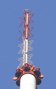
In order to obtain an approximately omnidirectional characteristic in the horizontal plane, two batwing dipoles are put together like a crossed dipole and both dipoles are fed with a phase difference of 90 °. Since this creates a circular polarization , two such crossed batwings are mounted on top of each other. One pair of antennas is equipped with left-handed circular polarization and the second pair with right-handed circular polarization. The sum of the two pairs of antennas causes a vertically linearly polarized magnetic field and a horizontally linearly polarized electric field in the far field. This construction was called the turnstile antenna.
For commercial use as a broadcast antenna, several such levels are stacked on top of each other. This construction was named Superturnstile antenna and can be seen on many transmission towers, such as the Berlin radio tower and the transmission mast in Mühlacker .

literature
- Alois Krischke: Rothammels Antennenbuch. 11th edition, Franckh-Kosmos-Verlags-GmbH, Stuttgart 1995, ISBN 3-440-07018-2
- Jürgen Tech: Do-it-yourself antennas. 2nd edition, cheek-Verlag GmbH + Co Druck KG, Stuttgart, 1980, ISBN 3-7724-0301-8
Individual evidence
- ↑ Angle principle for broadband antennas , accessed on May 18, 2016

