
Isolator (electrical engineering)

An insulator is a component in electrical engineering and power engineering with which bare (i.e. not self-insulated) electrical conductors are attached, held or guided without a significant flow of current through the fastening element. Insulators have to combine a high mechanical strength with a meaninglessly low electrical conductivity and therefore consist of solid insulating materials .
Insulators are used on overhead line masts , large antennas or in substations . Special bushing insulators isolate live conductors when entering a closed room from the wall, for example in the case of power transformers , large capacitors or shielding housings. The porcelain body of spark plugs is also functionally a bushing insulator, as it insulates the high-voltage ignition electrode through the metal cylinder head.
Electrical cables have insulation , an electrically insulating sheath.
Basics
materials

For the manufacture of insulators, only solids that are non-conductors and have the highest possible specific resistance and high dielectric strength can be considered.
The following materials are used (the values are intended as a guide and depend on temperature and frequency):
| material | specific resistance in Ω · cm |
Dielectric strength in kV / mm |
|---|---|---|
| Alumina ceramic | 10 14 | > 20 |
| steatite | 10 13 (at 20 ° C)
10 7 (at 600 ° C) |
20th |
| Porcelain (depending on type) | 10 11 -10 12 | 20th |
| Glass (depending on type) | 10 7 -10 16 | 10-40 |
|
Glass fiber reinforced plastics
(depending on production) |
10 10 −10 14 | 20-40 |
| Epoxy resins (depending on production) | 10 14 | > 10 |
In addition, insulators used outdoors must be permanently resistant to ultraviolet radiation and the effects of the weather (moisture, temperature fluctuations).
The fastening fittings at the ends of the actual insulator are usually made of cast metal and are attached with a high-strength cement.
Measures against leakage current
Outdoor insulators are subject to unfavorable environmental influences such as rain, snow or dust, and salt near the sea. As a result, contaminants can accumulate on the surface of an insulator outdoors, which over time form an electrically conductive film and thus compromise the insulating effect of the component. A leakage current then flows on the surface of the insulator , which usually only causes an insignificant transmission loss , but in unfavorable cases in the case of a sliding discharge , a flashover or an electric arc can lead to failure or even damage to the entire line due to a short circuit or earth fault .
In order to keep leakage currents despite the almost inevitable environmental effects as small as possible, it makes the leak paths as long as possible by the central stalk , additionally endows the insulator, which performs the actual support function with bell-shaped screens or ribs that the leakage current to a "folded" zig Force zack path, the length of which can exceed the overall length of the isolator by several times. The double-bell insulator, which Josiah Latimer Clark applied for a patent in England in 1856 and introduced for Prussia by Franz von Chauvin , is based on this and is still currently in use in many free low-voltage networks .
In addition, roof-like bevelled screens ensure that vertically hanging insulators on their underside ensure dry and therefore less conductive sections in the creepage distance, even when it rains.
Designs
Button / bell insulator

Sectional drawing of a double bell insulator

Bell insulator of an electric fence
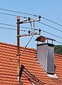
Roof stand for low voltage with bell insulators


Bell insulators are made from a wide variety of materials (plastic, ceramic, glass) in sizes from around 2 to 20 cm. They sit as an insulating "hat" at the end of a fastening hook. A bell-shaped cavity in the underside extends the creepage distance and can also be designed several times as a double bell . The live wire is attached with a special wire loop on the side of the upper part of the insulator in a circumferential groove. A bead below this groove, the groove plate , can carry the weight of the line.
Button insulators are particularly small designs without a pronounced bell shape on the underside and a short creepage distance.
Long rod insulator

Ready-to-install long rod insulators for high and extra high voltage

Long rod insulator of a railway overhead line

Long rod insulators mounted in a V shape prevent lateral deflection of the conductor


Long rod insulators are manufactured as elongated, rigid individual parts from a ceramic material in lengths of up to 2 meters. The insulating bodies are individually manufactured on special lathes and then glazed and fired .
Long rod insulators have long creepage distances and are highly puncture-proof, since the shortest path through the material that a voltage breakdown could take corresponds to the overall length and leads completely through the insulating material. Therefore, they are very widely used on high-voltage overhead lines.
Silicone insulator

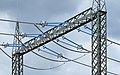
110 kV line with silicone insulators
Silicone insulators on an anchoring portal


Silicone insulators (more precisely: silicone composite insulators) are technically also long rod insulators, but are manufactured differently and have different properties. The central trunk is a rod made of high-strength glass fiber reinforced plastic , the silicone shades are either glued on individually or applied as a complete covering of the trunk in an injection molding process.
Compared to glass or ceramic insulators, they get less dirty, as silicones have a hydrophobic surface and this effect can be transferred to any layer of dirt . Therefore, they achieve the required insulating effect even with a shorter overall length and lower creepage distance extension and are lighter. Compared to classic ceramic long rod insulators, they have a "filigree" appearance due to the lower material thickness required; the screens are usually colored pale blue.
Cap insulator
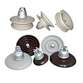
Cap isolator elements

Cap insulator chains for medium voltage

Cap insulator chains on a 380 kV line in a substation

.jpg)

Cap insulators consist of elements that can be lined up, each of which has a cap or bell-shaped insulating body made of glass or ceramic, with metal fittings attached to the top and bottom. Any number of these elements can be interlinked so that insulators of any length for all nominal voltages and applications can be assembled from them. For medium voltage, two to three elements are sufficient; for maximum voltages, chains of several meters in length are made from plate-sized caps. Since the elements can be moved inside one another, they form flexible insulators that are less sensitive to lateral forces than long-rod insulators.
However, the metallic connection fittings within the chain have a disadvantage, since they reduce the breakdown security. Therefore, overvoltages (e.g. lightning strikes in the conductor) can break down and mechanically damage cap insulators and are often replaced by other types of construction when new or reconstructed line poles are built. An anchoring portals cap insulators continue to be used because of their flexible adaptability.
A special form is the solid core insulator , in which two caps are combined to form a rigid ceramic element with higher dielectric strength.
Pressure hull

The loops (blue) of the insulating egg interlock, the ceramic body is only subjected to pressure. However, the creepage distance (red) is very short.

Guy isolator of a transmission tower. The insulating body sits on lubricated sliding surfaces between the steel band yokes.


A simple insulator design is the insulating egg , which consists of a ceramic body between two wire loops. Due to its construction and the position of the rope, it only experiences compressive stresses that ceramics can withstand particularly well.
As the insulation properties of eggs is low due to the short creepage distances, they are only suitable for the low-voltage range or for electric pasture fences, where minor losses are negligible. To increase the insulation voltage, several eggs with short pieces of wire can be placed one behind the other.
The guy isolator follows the same principle, with which the guys of live transmitter masts are isolated from the earth. Since guys have to absorb very high tensile forces, the isolator is constructed in such a way that it is only subjected to pressure.
Fittings
The conductor ropes are attached to the insulator with special clamps, the design of which depends on the purpose of use: In the case of support masts , only the weight of the conductor cable section has to be borne, while in the case of guy masts the significantly higher tensile force has to be absorbed by a special anchoring clamp .
Insulators for fastening overhead lines ( contact lines ) do not differ fundamentally from those for overhead lines, but must be designed for the special mechanical loads on the overhead line. Insulators for busbars have to support the heavy busbar. Often, an existing protective cover also serves as insulation for isolated fastening, as is the case with the Berlin S-Bahn.
High-voltage insulators are often equipped with a spark gap as a surge arrester in order to keep the high- energy arc away from the insulator in the event of an overvoltage (lightning strike) and to extinguish it through a suitable design.
Applications
Overhead lines
Low voltage (below 1 kV)
As insulators for earlier conventional telephone lines and low-voltage - transmission lines up to 1 kV rated voltage generally button-shaped ceramic body of the wire is secured with a special loop at the back are used. Standing on metal hooks, they are cemented or hempten, that is, screwed on with a hemp insert, with which they are mounted on masts or walls.
Ceramic insulating eggs are also used in this area for guy ropes or antenna ropes .
Medium voltage (1 kV to 30 kV)
For medium voltage , ribbed insulators made of glass or ceramic are usually used, which can either stand on the cross-beams of the masts or hang below them. Standing insulators enable lower mast heights and, due to their construction, offer more security against the conductor cable falling (if the insulator breaks, it falls on the crossbeam). Hanging insulators can evade lateral forces (e.g. from cross winds) by deflecting them to the side and are therefore less subject to bending. In addition, the live conductor cables do not pose such a great danger to birds that land on the traverse when they are suspended.
Medium voltage insulators are also produced and used in the open air from cycloaliphatic cast resin (see also: epoxy resin ). These isolators are used in the 12 kV, 24 kV or 36 kV range in particular for mast disconnectors. They differ in their overall height (decisive for the striking distance), the creepage distance and their mechanical strength.
In the interior (for example medium-voltage switchgear), insulators made of cast resin / epoxy resin are also used in various designs. In contrast to UV and weather-resistant cycloaliphatic casting resins, the casting resin for indoor use is based on bisphenol-A. Cast resin / epoxy resin insulators can have almost any shape compared to ceramic insulators and already contain conductors or components such as current or voltage converters. In addition to simpler rib supports, bushings can also be cast or, for example, fuse housings. In technical jargon, such insulation components are called medium-voltage bushings, entry tulips, entry blocks, fuse chambers or pole housings. These special products have a very large qualitative influence on functioning electrical insulation in the voltage range between 12 kV and 40.5 kV, especially with regard to a low partial discharge level (PD).
Casting resins / epoxy resins in the medium voltage range are mostly 2-component resins filled with quartz powder, which are stirred and prepared under vacuum, since bodies without cavities / bubbles are required to avoid partial discharges.
High and very high voltage

Insulators for high voltage (30 kV to 150 kV) are only designed as hanging with long rod or cap insulators. The technique of fastening the conductor cables does not differ from that used in the medium voltage range. For reasons of strength, two parallel single insulators are often arranged to form the double insulator. The same types are used for traction power lines as for three-phase power lines.

Insulators for high voltages (> 150 kV) are often manufactured as chains of two or more long rod insulators for high voltage (insulator chain). In Germany, two parallel insulators are generally used for 380 kV lines. For very high static requirements, three or four parallel long rod insulators or insulator chains can be used.
Isolators for high-voltage direct current transmission do not differ in principle from the types used for alternating voltage. Their stress at the same voltage is on the one hand lower because the pre-discharges (e.g. in damp weather) are lower. On the other hand, the voltage distribution along the insulators is potentially more inhomogeneous, which requires defined, homogeneous insulation resistance values.
Antennas
Transmission masts

Webbing isolator on the bracing of a transmission mast

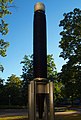
Insulated mast base of a transmission mast; the brown frustoconical component is the mast insulator


Special requirements are placed on the isolators of self-radiating transmission masts , because these must be able to carry voltages of up to 300 kV and loads of up to 1000 tons at high transmission powers. For this purpose, to isolate the guys belt insulators made of steatite and to isolate the towers and masts, hollow or solid bodies made of steatite are used, on which the overlay body that supports the tower or mast is fastened exactly. The mast insulator must be permanently under pressure from production and is stored in a pressing device until it is installed. The tower or mast is hydraulically lowered onto the isolator during installation.
Wire antennas
Guy ropes for transmission masts and overhead lines, but also wire antennas, are insulated with egg-shaped insulating bodies that have holes and grooves to accommodate the ropes.
Bushings
Bushings have an insulator that guides the conductor along the inside and insulates it from a metallic wall through which it protrudes. Insulator bushings are required in the power grid for sealed entry into buildings, housings, underground cables, current and voltage converters or transformers.
Smaller designs can be found on spark plugs or capacitors with metal housings. The insulator has a flange or an annular solderable metal surface for mounting in a hole on the outside. The inside lead has soldered or screw connections. Often, concentric layers of metal foils are inserted into the insulator body, which act as cylindrical capacitors and control the course of the electrical field strength in the radial or axial direction. Such bushings are also referred to as capacitor bushings.

Schematic representation of a 52 kV bushing

Bushings for low and medium voltage

110 kV and 220 kV bushings

380 kV bushings
1MV bushing insulator


Overload damage
Every real insulator can only isolate up to a certain voltage, up to which it does not allow any noteworthy currents to pass through, i.e. its conductivity is negligible. It thus represents a finite, albeit mostly very high electrical resistance. The value for the maximum voltage load depends on the material as well as the surrounding medium as well as the frequency (only available with alternating current and pulsating direct current ) and temperature.
If the voltage is too high in overhead lines, if the surrounding media (e.g. air) have a lower electrical resistance or a lower dielectric strength, there may be a flashover first or, if the environment (e.g. vacuum) has a higher resistance or dielectric strength . has a higher dielectric strength or only a cable sheath separates the conductors involved, a voltage breakdown occurs, which creates a short circuit .
When dimensioning overhead line insulators, not only their own insulation capacity but also that of the surrounding medium must be taken into account in order to prevent voltage flashovers.
In general, all insulators can conduct (higher or high) electrical currents, at least for a short time, if an extremely high amount of energy is used, for example by applying a sufficiently high voltage (for example when the breakdown voltage is exceeded ) or by (strong) heating (i.e. with very high temperatures ), whereby the amount required for this depends on the material. The insulator is at least damaged, and often completely destroyed, and loses its function. For example, glass can also conduct electricity, but it melts in the process.
Despite the fact that insulators according to the band model have filled all occupied bands, these are only really non-conductive at absolute zero , as more and more electrons migrate from the most occupied bands to the lowest unoccupied band as the temperature increases. With increasing temperature and increasing frequency , the dielectric strength decreases, at high frequency the reduced dielectric strength can be clearly determined.
At high temperatures, insulators increasingly behave like semiconductors , but still hardly conduct any current, as the large band gaps of a few electron volts for charge carriers can hardly be jumped.
Historic designs

In the early days of electrical power transmission, insulators on high-voltage overhead lines were also designed with specially shaped oil channels. With these insulators, also known as oil insulators, the oil was introduced into specially shaped grooves that are circularly guided around the insulator after assembly. It was used to minimize unwanted leakage currents from the conductor to the earthed suspension as a result of environmental influences such as moisture (fog, rain). In addition, oil is lighter than water, so that the electrically non-conductive oil always remains on the surface up to a certain degree of contamination and thus represents an electrically insulating barrier.
Oil insulators are no longer used today because of the high maintenance costs, pollution problems and the availability of more efficient options for preventing leakage currents.
Isolator museums
An isolator museum is located in Lohr am Main in a listed former transformer house on Haaggasse . In addition to a large part of the private collection of the owner, a trained high-voltage electrician, there are also individual items on loan from other insulator collectors. The different sizes and designs of insulators as well as their historical development are shown.
Another museum that focuses on the manufacture of ceramic insulators and their manufacture from kaolin is located at the location of the former Margarethenhütte in Großdubrau in Upper Lusatia, Saxony. The Margarethenhütte, which last traded as VEB Elektroporzellan Großdubrau , was one of the leading manufacturers of high-voltage insulators in Europe until it was liquidated as a result of the political change in the GDR.
literature
- Gustav Benischke : The porcelain insulators . Julius Springer, Berlin 1921.
Web links
- Isolator Museum of the City of Lohr am Main - Vormwald Collection
- Margarethenhütte Museum, Großdubrau
- Experiment by the Leibniz University Hannover on the conductivity of glass
Individual evidence
- ↑ P. Grosse: Free electrons in solids . Springer-Verlag, 2013, ISBN 978-3-642-95344-6 ( limited preview in Google Book Search [accessed August 2, 2016]).
- ↑ O. Madelung, AB Lidiard, JM Stevels, E. Darmois: Electrical Conductivity II / Elektroleitungphänomene II . Springer-Verlag, 2013, ISBN 978-3-642-45859-0 ( limited preview in Google book search [accessed August 2, 2016]).
- ^ Theodore L. Brown, Bruce Edward Bursten, Harold Eugene LeMay: Chemistry: Studying compact . Pearson Deutschland GmbH, 2011, ISBN 978-3-86894-122-7 ( limited preview in Google Book Search [accessed September 3, 2016]).
- ↑ Components made of Al2O3 ceramic and their post-processing with diamond tools. (PDF) p. 2 , accessed on November 4, 2016 .
- ↑ Ceramic insulators with high dielectric strength made from aluminum oxide ceramic. In: oxidkeramik.de. Retrieved June 13, 2016 .
- ↑ Technical information Steatit C221. Retrieved June 13, 2016 .
- ^ Hans-Jürgen Bargel, Günter Schulze: Material science . Springer-Verlag, 2013, ISBN 978-3-642-17717-0 ( limited preview in Google book search [accessed November 4, 2016]).
- ↑ Product information porcelain C 110. (PDF) Retrieved on June 13, 2016 .
- ^ Friedemann Völklein, Thomas Zetterer: Practical knowledge of microsystem technology: Fundamentals - Technologies - Applications . Springer-Verlag, 2008, ISBN 978-3-8348-9105-1 ( limited preview in Google Book Search [accessed November 4, 2016]).
- ↑ Electrical breakdown or flashover. In: der-wirtschaftsingenieur.de. Retrieved June 13, 2016 .
- ↑ GRP technical data. In: pluessag.ch. Retrieved June 13, 2016 .
- ↑ Technical data sheet ER2188 epoxy resin. (PDF) (No longer available online.) Archived from the original on June 13, 2016 ; accessed on June 13, 2016 .
- ↑ Arthur Wilke: The electricity . Spamer, Leipzig 1899, p. 110.
- ↑ Product information from Lapp , accessed on July 28, 2020
- ↑ Product information from Pfisterer , accessed on July 28, 2020
- ^ Friedrich Kießling , Peter Nefzger, Ulf Kaintzyk: Overhead lines. Planning, calculation, execution. 5th, completely revised edition. Springer, Berlin a. a. 2001, ISBN 3-540-42255-2 , section 9.5.
- ↑ Helmut Böhme: medium voltage technology. Calculate and design switchgear. 2nd, heavily edited edition. Huss-Medien - Verlag Technik, Berlin 2005, ISBN 3-341-01495-0 .
- ↑ Heinrich Frohne, Karl-Heinz Locher, Hans Müller, Franz Moeller: Moeller Fundamentals of Electrical Engineering . Springer-Verlag, 2005, ISBN 978-3-519-66400-0 ( limited preview in the Google book search [accessed September 8, 2016]).
- ^ Wilhelm Raith: Electromagnetism . Walter de Gruyter, 2006, ISBN 978-3-11-019928-4 ( limited preview in Google Book Search [accessed September 8, 2016]).
- ^ Myer Kutz: Handbook of Measurement in Science and Engineering . John Wiley & Sons, 2015, ISBN 978-1-118-45327-8 ( limited preview in Google Book Search [accessed May 5, 2016]).
- ↑ Manas Chanda, Salil K. Roy: Plastics Fundamentals, Properties, and Testing . CRC Press, 2008, ISBN 978-1-4200-8061-2 ( limited preview in Google Book Search [accessed May 5, 2016]).
- ↑ Bernard Diu, Claudine Guthmann, Danielle Lederer, Bernard Roulet: Fundamentals of Statistical Physics: A textbook with exercises . Walter de Gruyter, 1994, ISBN 978-3-11-088929-1 ( limited preview in Google book search).
- ^ Günther Oberdorfer: Short textbook of electrical engineering . Springer-Verlag, 2013, ISBN 978-3-7091-5062-7 ( limited preview in Google Book Search [accessed July 20, 2016]).
- ↑ William Oburger: The insulating materials in electrical engineering . Springer-Verlag, 2013, ISBN 978-3-662-26196-5 ( limited preview in Google Book Search [accessed July 20, 2016]).
- ↑ Klaus Lüders: Relativistic Physics - from electricity to optics . Walter de Gruyter, 2015, ISBN 978-3-11-038483-3 ( limited preview in Google Book Search [accessed May 5, 2016]).
- ^ AE van Arkel, P. Assmann, G. Borelius, G. Chaudron, EJ Daniels: Pure metals: production · properties · use . Springer-Verlag, 2013, ISBN 978-3-642-99695-5 ( limited preview in Google Book Search [accessed on May 5, 2016]).
- ↑ NA Semenoff, NA Walther: The physics of dielectric theory . Springer-Verlag, 2013, ISBN 978-3-642-91334-1 ( limited preview in Google book search [accessed May 5, 2016]).
- ^ H. Behnken, F. Breisig, A. Fraenckel, A. Güntherschulze, F. Kiebitz: Electrical engineering . Springer-Verlag, 2013, ISBN 978-3-642-50945-2 ( limited preview in Google Book Search [accessed on May 7, 2016]).
- ↑ David Wenzel: Ceramics and ceramic combinations for fine particle separation with the help of thermally induced potential fields and electron emissions . Forschungszentrum Jülich, 2012, ISBN 978-3-89336-820-4 ( limited preview in the Google book search [accessed June 12, 2016]).
- ↑ The metal bond. In: www.uni-ulm.de. Retrieved June 12, 2016 .
- ^ Zipp : The electrical engineering. Effects and laws of electricity and their technical applications. Volume 1. 6., completely revised edition. Edited by Max Reck. CA Weller, Berlin 1940, pp. 592-593.