Busbar
A busbar is a supply line made of rigid material for the electrical current for electrically driven rail vehicles and other movable electricity consumers, e.g. B. crane systems.
Conductor rails for electric railways
Busbars for electric railways are now generally made of aluminum with a rolled-in, wear-resistant stainless steel running surface or of the cheaper but less conductive soft iron, more rarely of steel.
Use of the running rails
The closest possible way of supplying electrical energy to a railway externally is to use the pair of running rails, each rail forming an electrical pole and the sleepers, in addition to mechanical fastening, also having an insulating function . In fact, this technology was used in the early days of electric tram operation, for example on the electric tram Lichterfelde-Kadettenanstalt and the Ungererbahn , but at (in Lichterfelde) comparatively low voltages of around 150 volts. However, these caused problems at the crossings and freely accessible places as soon as a person or animal stepped on both tracks at the same time. In addition, discharges through the soil caused problems. After a short period of operation, the rails at the crossings had to be disconnected from the power supply and the crossings had to be driven over with momentum. The axles or wheel sets of the vehicles had to be electrically separated in the middle or on the individual wheels by insulation , which was technically feasible, but complex and therefore expensive. In addition, special effort must be made for turning loops or track triangles so that opposing polarities are not connected. Switches and crossings are more complex. In order to maintain the separation, the frogs, and also the double frogs at crossings, must be permanently isolated from all connected rails and from the full driving voltage; every breaking insulation joint causes a driving voltage short circuit.
Because of the disadvantages described, the power supply via the running rails is no longer used in rail operations today. In the case of model railway systems, on the other hand, this technology of power supply is widely used ( two-rail, two-wire system ).
The side busbar
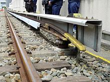
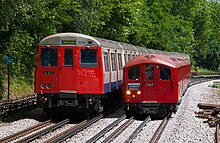
In electric railways, busbars are usually installed alongside the track . In the London and southern England area there is an extensive network of underground, suburban and long-distance railways, which is equipped with conductor rails in the central and lateral positions.
The use of a third rail, which is only used to supply power, but not to carry the vehicle's weight, has the advantage that it can be better insulated and can therefore be used with higher voltages (up to 1500 V, compared to 200 V with power supply via running rails) . However, for safety reasons, a low-lying conductor rail can only be used for railways whose track structure may not be walked on, so that it is mainly used for underground trains, but also for some S-Bahn and long-distance trains. With the power rail supply, a small and inexpensive clearance profile can be implemented, especially for tunnel tracks .
As a rule, several current rail pantographs are attached to the locomotives or multiple units . This makes it possible to functionally bridge gaps in the conductor rail, for example in switch areas . In this way, the power supply is also secured in the event that a sanding pad falls off at the predetermined breaking point when it comes into contact with an obstacle . At the beginning and end of busbar sections, the busbar is led away to the side or upwards against the spring action of the current collectors, in order to allow the current collectors to slide smoothly onto the busbar.
Since direct current railways are usually operated with high currents (2 - 20 kA compared to the 1.5 kA of 15 kV alternating current railways), the lower voltage drop due to the larger cross-section of busbars (compared to an overhead line ) has an advantageous effect .

Busbars close to the ground have the following advantages over overhead lines:
- Maintenance is easier and cheaper because no climbing aids are required. There is no risk of falling for the fitters.
- Installation and construction are cheaper because masts and mast foundations as well as anchoring for overhead lines and support wires are not required.
- A busbar is much more wear-resistant and more robust against pantograph derailments, which regularly lead to serious damage in an overhead line.
- Despite the higher use of material, busbars close to the ground are e.g. B. in metropolitan areas often cheaper to set up and operate than an overhead contact line, which is difficult to install in confined spaces.
Busbars close to the ground have the following disadvantages compared to overhead lines:
- Danger for people and animals in the track structure due to the proximity to the ground.
- Elaborate construction (and cabling) in areas with many switches
- Vehicles need pantographs on both sides
- Limitation of the transmission voltage to 1500 V, as dirt occurs near the floor, which disrupts the insulation.
- Due to the inflexible shoe track of a rigid conductor rail, the speed is limited to around 120 km / h. High-speed traffic above around 150 km / h is hardly possible.
- Problems with drifting snow and clearing snow with snow blowers
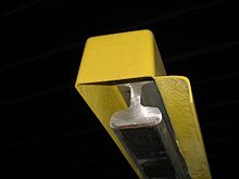
Busbars can be installed from above (e.g. small-profile U-Bahn Berlin , Metró Budapest , tunnel sections of the Martigny-Châtelard-Bahn in Switzerland and the connected railway line Saint-Gervais-Vallorcine in France, routes in the south-east of England including the Network of London Underground ), from below (e.g. large-profile U-Bahn Berlin, U-Bahns Hamburg , Nuremberg , Munich , Vienna and S-Bahn Berlin ) or from the side ( S-Bahn Hamburg ). Busbars coated from above and from the side offer the advantage of simpler support, but protection against accidental contact is difficult and has limited effectiveness. Busbars coated from below are mechanically more demanding, but protection against accidental contact is more effective. In Germany , busbars are provided with an insulating protective cover as far as possible.

Busbars coated from above or below are interrupted in switches in the tongue area where the current collectors have to run up or down laterally. If this is not justifiable in terms of driving dynamics, because an uninterrupted power supply is required at the point in question, for example because of the gradient, a busbar run-up is installed at the corresponding point. Busbars coated from below are raised at these points, and busbars coated from above are lowered. In addition, an inclined sliding surface is arranged on the track side. Because the protection against accidental contact is limited on a conductor rail, conductor rail entrances are marked with a warning sign.
The London Underground uses a system with two conductor rails, with one conductor rail (+420 V, +630 V in mixed operation with rail) running on the side and another (−210 V, 0 V in mixed operation) in the middle of the track. In the middle there are busbars in VAL and similar systems like the London Stansted Airport People Mover.
The Glasgow Subway had two more next to the lateral busbar for 600 V DC, which ran from 1935 to 1977 in the amount of the side windows of the car. They were used to power the interior lighting with 220 V alternating voltage.
If work in the track area requires safe disconnection of the conductor rail, current test boxes and short-circuiters are used (the illustration shows the application with a conductor rail that is open at the top).
Power rails sunk under the runways
From 1887, Siemens & Halske used a system in Budapest and also in Vienna and Berlin in which the two rails of the tramway track consisted of two halves with a slot open at the top. Below the rail on one side ran a channel in which two ladders made of thick angle iron were located. These two conductor rails were attached to insulating brackets in the form of horseshoes at intervals of several meters. One pole was on the left and the other on the right. The canals were walled in. They only communicated with the open air through the slit between the rails. There was a plate on the vehicles with two rotating metal tongues at the bottom. The plate ran vertically in the slot in the rail with the two conductors and touched one of the two lines with one of the two metal tongues. One of the two lines was the outward and the other the return line. The voltage difference was between 300 and 600 volts. The system was used in Budapest from 1887 in trial operation on the test route Westbahnhof – Ringstrasse – Királystrasse with a gauge of 1000 millimeters and from 1889 to around the mid-1920s in downtown Budapest on a route with a gauge of 1435 millimeters.
The Wuppertal suspension railway uses a steel rail for power supply, which is mounted on insulators under the driving profile and is scanned by two spring-loaded pantographs per car.
The recessed center busbar

Where the installation of an overhead line was undesirable for reasons of site protection , e.g. As early as the late 19th and early 20th centuries, trams were equipped with power rails that were sunk into the pavement between the rails , for example on Vienna's Ringstrasse or when crossing Unter den Linden in Berlin. A fold-out sliding contact attached under the vehicle floor reached into the narrow gap in the pavement and established the electrical connection to the vehicle. The high maintenance costs, the big problems with snow and ice and the necessary complicated switch constructions made the tram operators abandon this technology again.
An exposed central rail was used by the London Post Office Railway from 1927 to 2003 and the second technical generation of the Post-U-Bahn in Munich between 1966 and 1988. Both were used exclusively for the transport of mail and ran automatically in their own tunnels.
APS - Alimentation par le Sol
The technology Alimentation par le Sol (APS for short, German about power supply from the ground ), which revived the medium current rail for trams, comes from France and was developed by Innorail, which is now part of the Alstom Group. It was first used on the Bordeaux tram .
In this system, there is a busbar between the two rails that can carry 750 volts DC. The power rail is divided into individual sections. Each section consists of an eight-meter-long live rail and a three-meter-long insulated section. If the busbar is run over by a tram train, it sends out a coded signal via radio that applies voltage to the section of the busbar that is completely under the vehicle. A maximum of two of the eleven meter long segments can be switched on at the same time. Before the train leaves a segment, it is switched off and grounded for safety reasons. So far, this technology has only been offered by Alstom.
The system is also used on other trams - since 2011 on the Angers tram and the Reims tram . The Orléans tram wants to use APS on a new line and the new Al Sufouh tram in Dubai will be equipped with it.
TramWave
Ansaldo STS has also developed a technology with a medium busbar. In the "TramWave" system, the double-row center busbar is divided into individual sections, each 50 cm long. When driving over a permanent magnet on the pantograph pulls a contact plate below the roadway upwards, so that an electrical contact is made with the busbar via the plate. The system was first tested for electric buses in Trieste in 2000, back then under the name STREAM for "Sistema di TRasporto Elettrico ad Attrazione Magnetica". However, the STREAM project did not get beyond a short test phase on bus route 9. In Naples, a 600 m long test track was set up in the city, on which converted Sirio articulated vehicles operate.
In July 2012, the technology was licensed to a Chinese consortium and adapted there to new Chinese tram designs. Subsequently, CNR built the new lines in Zhuhai with Tramwave busbars in order to maintain operations or to be able to resume quickly even in the case of the frequent typhoons in the area. The first line went into operation in June 2017.
Primove
Bombardier's "PRIMOVE" also uses a power supply divided into sections that are only activated when the vehicle is driven over. In contrast to Alstom's APS and Ansaldo's TramWave, however, it is based on inductive energy transmission and not on direct power supply via grinding shoes and is therefore not a power rail in the narrower sense. There are test tracks on the Augsburg tram, among others . Bombardier "PRIMOVE" was awarded the innovation prize of the Privatbahn Magazin in 2012/2013 (in the multiple unit category) .
This technology, which was developed for trams, has now been adapted for the rapid charging of battery buses, in which the cars stop at the stops above an induction plate about five by two meters. This technology, which contradicts the original purpose of the power rail as a battery-free power supply, is also marketed as Primove. Corresponding test tracks exist in Braunschweig (since May 2014) as well as Mannheim and Berlin (from summer 2015) in passenger service.
Overhead conductor rails

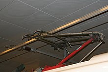
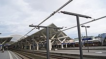
Occasionally or in special cases, busbars can also represent a section of an overhead line; so z. B. in workshops or in tunnels with a restricted clearance profile , such as in the north-south long-distance railway tunnel in Berlin, where the 15 kV AC voltage is supplied via an overhead conductor rail . In recent times, electric trams have often not been provided with a contact wire but an overhead conductor rail in tunnels. In terms of construction, a normal notch contact wire is usually clamped into an aluminum support profile.
The advantages of busbars compared to conventional contact lines include easier laying (e.g. in the area of the switches), higher operating currents (thus in some cases dispensing with feed lines), higher electrical and mechanical operational reliability and lower maintenance costs. The disadvantages include higher construction costs, which in the case of underground systems are compensated for by the lower overall height and the associated tunnel cross-sections.
Due to the small installation height required, overhead conductor rails are also used for conversions in older tunnels (e.g. Gemmenicher Tunnel , Arlberg Tunnel ) with a lower clearance profile. Another area of application is use in depots and on loading platforms. For this purpose, the busbar can be swiveled or lifted, which enables or simplifies the use of lifting jacks and crane systems.
The use of the overhead conductor rail also makes sense due to the high availability and the resulting operational reliability. Furthermore, cables laid parallel to the overhead line can be omitted or minimized in long tunnels, since the conductor rail normally has a cross-section of 1300 mm² copper equivalent, which is around six times larger than that of a chain overhead line.
The overhead conductor rail was tested on the Zurich S-Bahn in the 1980s . In 1984 a test facility was built in Zurich-Opfikon train station. In 1986, positive results led to the decision to equip the new Museumsstrasse station .
In the late 1980s, an overhead conductor rail for a speed of 160 km / h was tested over a length of one kilometer in the Simplon tunnel . In this way, an expensive lowering of the track system was to be avoided in order to produce the particularly large clearance profile required for the Rolling Highway . Before this test, overhead conductor rails had been used at speeds of up to 110 km / h in Switzerland and up to 80 km / h internationally.
The use of an overhead conductor rail was considered in the in-depth planning of the north-south long-distance railway tunnel begun in 1993 . This resulted in multi-layered discussions that ultimately led to the decision for the overhead conductor rail. The approval procedure for the electrotechnical systems of the federal railways was applied for in June 1995. Among other things, evidence of accidents was prepared and road tests were carried out. In 1996 the German Federal Railway Authority approved a type of overhead conductor rail for 140 km / h, which was later to be used in the underground station of Berlin Central Station. With a cross-section of 2220 mm 2 aluminum, the continuous current carrying capacity is 2400 A.
In Germany, Furrer + Frey overhead conductor rails were first installed during the electrification of the Murg Valley Railway, the first stage of which went into operation in June 2002. Overall, the overhead conductor rail was installed in the section between Rastatt and Raumünzach over a total length of 1.8 km in tunnels and short open intermediate sections .
In Switzerland, the Federal Office of Transport approved the use of the overhead conductor rail for 160 km / h; it has since been used in the four-kilometer-long Kerenzberg tunnel.
A three-kilometer test section in the Lower Austrian Sittenberg Tunnel was initially approved for 200 km / h in 2004. In mid-August 2004, this section was driven with the ICE S at 260 km / h. The authorities of Austria and Switzerland then announced the approval of the system used for 250 km / h (status: 2004). In autumn 2010 there was proof of 230 km / h in the same tunnel. The approval process is ongoing (as of mid-2011). For the Koralm tunnel , an operating speed of 250 km / h with a tunnel cross-section of 40.3 m² using the overhead conductor rail was applied for for approval. The Ceneri base tunnel, which is also equipped with an overhead conductor rail, is to be driven at 250 km / h (from 2020). Operational tests for 250 km / h have been carried out, test drives up to 302 km / h were achieved.
Due to the narrow spacing between support points (from 8 to 12 meters), the overhead conductor rail can only be used effectively in tunnels. In some cases, for example on the main line of the Copenhagen S-Bahn between Københavns H and Østerport, the overhead conductor rail was also continued between the tunnel sections in order to avoid multiple changes in the type of contact line.
Overhead conductor rails and the associated structural designs of the transitions and separations were certified by Eisenbahn-Cert (EBC) for 140 km / h in accordance with the specifications of the Energy TSI for the interoperable European rail network (status: 2006). The company Furrer + Frey built by 2011 more than 1000 km overhead conductor rails in 15 countries.
Overhead conductor rails worth 37 million euros are to be installed in the Stuttgart 21 project .
Nominal voltages for railways with power rails
Depending on the age of the system definition, the economically and technically sensible voltage level was set at different levels. While in the early days of electric train conveyance 600 V was considered sufficient, with the increase in the power to be delivered in the networks, one was forced to increase the nominal voltage in order not to let the currents to be transmitted become too high (transmission losses).
The upper limit of the voltage on direct current railways with a busbar on the side is currently 1500 V. The insulation distances and the distances for an impermissible approximation are so small that these properties make it possible to build busbars close to the ground. However, under unfavorable circumstances (heavy soiling of the isolators, as well as heavy exposure to snow and rain), the insulation effort can be more extensive.
The return line is parasitic via the rails. The well-known exception is the London Underground. AC voltage systems can only be used for two-rail feed.
Due to the significantly higher currents in direct current railways (P = U · I), there is a tendency towards higher flying sparks and burns at the contact surfaces of the pantographs, which, however, are compensated for by the larger contact surface on the grinding shoe.
Some examples of voltages used are:
- In Germany: 600 V on the Berlin-Lichterfelde-Ost suburban railway from 1903 to 1929, 750 V Berlin S-Bahn since 1924, 1200 V Hamburg S-Bahn since 1939.
- In France from 1925 to 1976: 1500 V Chambéry – Modane (Maurienne, access to the Mont Cenis tunnel ).
- Line 4 of the Guangzhou subway : 1500 V since 1999, analogous to German S-Bahn systems, no snowfall.
New systems with higher voltages are not known. After the introduction of static inverters, no new busbar systems were designed with direct voltage.
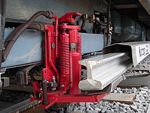
Power is supplied from the busbar to the vehicle via so-called grinding shoes , which are attached to the side of the vehicles' bogies. In this system, the electricity is returned via the wheels and rails, as is the case with other electric railways.

Transmission from the busbar to the vehicle
The power supply from the busbar to the vehicle is principally made via sliding contacts ;
- for lateral busbars via so-called grinding shoes, which are attached to the side of the bogies or the car body of the vehicles.
- with overhead conductor rails using standard pantographs , which are mostly designed primarily for the more common overhead lines .
The current is generally returned via the metal wheels and rails. An exception is, for example, the London Underground , in whose network a second conductor rail in the middle of the track is used as a return line for electrochemical reasons.
distribution
In Germany , busbars are used in the (real) subways operated with direct current in Berlin , Hamburg , Munich and Nuremberg and the S-Bahn trains in Berlin (750 V ) and Hamburg (1200 V). The Wuppertal suspension railway is also supplied with energy via a power rail.
Some subways, such as in London and Milan , are operated with two conductor rails on the track , one of which is laid in the middle of the track between the running rails. Avoiding in this way any stray current - corrosion in underground metallic structures such as pipelines.
In the north-south long-distance railway tunnel in Berlin, in the Leipzig City Tunnel , in the terminus of the Dresden Airport S-Bahn and also in several underground lines in Switzerland, instead of the classic overhead line with contact wire, there are power rails for 15,000 volts AC in the Full profile tunnel sections. In the course of renovation and safety retrofitting in the Arlberg Tunnel in Austria, overhead conductor rails were installed instead of a classic overhead line in 2010.
In southern England , many overland routes were electrified with power rails (660 V DC) from the 1930s onwards, as the clearance profile there was too small (especially too low) to enable electrification with overhead lines without major modifications. The Eurostar units also ran on these routes before the High Speed One was completed . In transport come here only multiple units are used, which in some cases also in the long-distance transport are used. In addition, locomotives that are equipped for operation via conductor rails are also used in long-distance and freight transport and supplemented by diesel locomotives .
Application obstacles for long-distance railways

In the case of long-distance railways, busbars located on the side or below have not prevailed over a large area, mainly for technical reasons. The main obstacles are:
- Busbars can only run through a turnout on the side of a branch track if they
- be painted from the side (S-Bahn Hamburg) or
- have a busbar run-up (S-Bahn Berlin).
In the other cases, a busbar coated from above or below must always end in front of the switch in order to then be continued behind the switch, the power supply of the individual busbar sections being carried out using high-voltage cables and disconnectors.
- Without interrupting the power supply, turnout sections can only be driven through by multiple units with a corresponding number of grinders and - at least partially - continuous power lines.
- A train operation with locomotive-hauled wagon trains without additional pantographs on the wagons is technically possible, but would be limited to non-powered swinging due to gaps in busbars at the switches and especially in the long switch routes at the station exits, as the locomotive is temporarily not supplied with power.
- For higher power over longer distances, a higher voltage is more favorable, as the currents flowing here are smaller. To do this, the distances between the rail and the pantograph must be greater. This is often done more cheaply with overhead lines (instead of using insulators or plastic intermediate layers) .
- As the distance between the substations increases and the power consumption increases, line losses and voltage drops due to line resistance become increasingly noticeable. The best way to solve this problem is to increase the tension. However, if the voltage is higher, the minimum required insulation distance also increases. Flashovers are possible at one centimeter per kilovolt. With an additional safety margin, the profile-free laying of the busbar would hardly be possible, and correspondingly insulated pantographs on the vehicles, which are also at risk of contamination at this point, would also be difficult to keep operationally reliable. Therefore, the maximum voltage that can be used for the conductor rails, about 1500 V .
- The risk of an electric shock from inadmissible approach and contact (e.g. by children, animals or even careless adults) is much greater than with overhead lines. Ground-level crossings with streets through which unauthorized persons could get to the conductor rails are prohibited for new systems. However, there are still level crossings with streets and paths on the S-Bahn in Hamburg and Berlin.
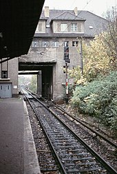
In principle, railway tracks can be provided with overhead lines and power rails at the same time. This was the case, for example, with the Hamburg S-Bahn between 1940 and 1955. Even the Paris train station Saint-Lazare had 1,967 to 1,978 tracks with both systems (busbar with 750 V DC and catenary at 25 kV AC at 50 Hz) on. A current example is the Birkenwerder station (b Berlin) , on which both platform tracks and three sidings are equipped with both power rails and overhead lines. However, problems can arise with the mutual influence of the circuits, as long as at least one - as in Birkenwerder - is not fed in galvanically isolated. As a result of the voltage drop along the rails, direct current can flow from the busbar system via the low-resistance transformer windings of the locomotives and substations into the catenary system (rarely the other way around). If one of these systems is a direct current and one is an alternating current system , undesired direct current bias of the transformers can occur both in the alternating voltage traction vehicles and in the substations of the alternating voltage system.
For this reason, double electrification with overhead contact lines and busbars is only planned if this is necessary for cost or operational reasons. (Example Birkenwerder: Necessary bringing of suburban trains of the "Sputnik traffic" with 15 kV locomotives to the platform of the 750 V direct current S-Bahn for the purpose of an important transfer point. A second platform for separation could not be built for reasons of space.)
The London Underground uses special return rails. They are designed to keep the drive back flow away from the cast iron tunnels. In the long-distance railway network, the return lines are connected to the running rails. However, the special return line is only used in the long-distance network where underground trains also run. Examples are the Gunnersbury – Richmond junction, which is shared by the District Line , and Queens Park – Harrow & Wealdstone of the Watford DC Line .
The supply of catenary and busbars with the same type of current as in the early days in parts of the Paris subway network or in the stations of the Maurienne Culoz – Modane route is comparatively unproblematic. Line B of the Buenos Aires subway was only equipped with overhead conductor rails in addition to the side rails after 2000 because of the use of cars from different origins.
Other technical applications
The use of busbars is not limited to railways only. Bridge cranes and their trolleys as well as laboratory and workshop systems with semi-mobile power consumers for alternating or three-phase current are also supplied with power rails. The wagons of a ghost train run guided by a strongly curved rail, on which there are busbars on the side or next to it on the floor, which are fed with protective low voltage. On the oval of an electric go-kart track, iron plates laid in strips connected to the two poles of the power supply allow driving with a fairly free choice of lane, as long as the car is not sideways. The bumper car ride can be driven all over the place, because it rolls on a continuous steel plate and a springy metal bracket grinds under a tensioned wire mesh as the second pole of the power supply.
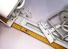
Another application is lighting technology with movable headlights, e.g. B. in shop windows, from 1975 also for the living area. These rails are mounted in or on the ceiling, wall, floor or in showcases and have up to four silver-plated or nickel-plated copper rails, insulated in the aluminum profile connected to the protective conductor and safe to touch, which supply the switchable lights via up to three circuits and thus provide lighting effects or night lighting enable.
For the purposes of conveyor technology, busbars are often designed as multi-core conductor rails in plastic carrier systems with copper conductors or as multi-core systems laid in parallel with individual rails in a plastic-copper combination.
Power rails on model railways
The model railway industry produces no prototypical functioning power rails on its side due to the high installation costs. The corresponding vehicle models, like the other vehicles, are also supplied with power via the two running rails.
An electrically insulated middle rail for power supply, on the other hand, was widespread in the early days of electric model railways. All electric tinplate tracks were equipped with center rails. It was only after the end of the Second World War that the first model railways with a two-rail, two-rail system appeared. The Trix Express system with the electrically insulated center rail was still in production until 1997 (a few years after the takeover by Märklin), but is enjoying increasing popularity again among collectors and friends of historical model railways. Märklin had already replaced the earlier third "middle rail" in 1953 with the so-called point contacts : These are sheet metal teeth that protrude up through holes in the sleepers of the conductor rail, which runs concealed under the track, and are brushed by a slider suspended between the wheels of the locomotive to collect current become. This system is still in use today.
Also Lego had 12V operated at the first railways a busbar in the center between the track rails. The current was transferred to the motor via sliding contacts. Since the tracks themselves were not conductive, two parallel busbar strings had to be run, which meant that track systems were not allowed to have reversing loops that led back to the same track.
Electric model car racing tracks , only two-lane for the children's room or multi-lane in slot car halls, lead power rails next to the track slots.
Metaphorical use
In US politics, the term “third rail” is used to denote a taboo subject or a matter that a politician shouldn't be touching.
Web links
Individual evidence
- ↑ George Watson: Glasgow Subway Album . Adam Gordon, Chetwode 2000, ISBN 1-874422-31-1 , pp. 6 (English).
- ^ The electric light rail in Budapest. In: Weekly of the Austrian Association of Engineers and Architects , year 1891, No. 1/1891 (XVI. Year), p. 2 ff. (Online at ANNO ). .
- ↑ Dr. Leo Graetz: Electricity and its applications, 18th edition, 1917, Stuttgart, p. 628
- ^ Drawing in Győző Zemplén: Az elektromosság és gyakorlati alkalmazásai, 1910, Budapest. P. 472
- ↑ https://www.youtube.com/watch?v=IC-HT56o5l4 ( Memento from December 7, 2013 in the Internet Archive )
- ↑ Archived copy ( memento of the original from June 19, 2012 in the Internet Archive ) Info: The archive link was inserted automatically and has not yet been checked. Please check the original and archive link according to the instructions and then remove this notice.
- ↑ The STREAM project on www.tpltrieste.it ( Memento of the original from June 19, 2012 in the Internet Archive ) Info: The archive link was inserted automatically and has not yet been checked. Please check the original and archive link according to the instructions and then remove this notice.
- ↑ http://www.sirio.tw/images/documents/TramWave%20eng.E.pdf ( page no longer available , search in web archives ) Info: The link was automatically marked as defective. Please check the link according to the instructions and then remove this notice.
- ↑ http://www.railway-technology.com/news/newsansaldo-transfer-tramwave-technology-chinese-jv
- ↑ Zhuhai tramway starts trial operation . November 12, 2014.
- ↑ First induction bus stops in Mannheim under construction . golem. May 2015. |
- ↑ PRIMOVE: From summer 2015 E-Bus Berlin with new technology clean through the German capital . Bombardier. March 2015. Archived from the original on April 27, 2015. Retrieved on April 20, 2015.
- ↑ a b c d Werner Kraus: Overhead conductor rail in the north-south tunnel in Berlin . In: The Railway Engineer . tape 57 , no. 8 , 2015, ISSN 0013-2810 , p. 27-31 .
- ↑ a b c d e Franz Kurzweil, Beat Furrer: Overhead conductor rail for high travel speeds . In: Elektro Bahnen , Issue 8, Volume 109, 2011, pp. 398–403.
- ↑ Announcement Successful conductor rail tests in the Simplon tunnel . In: Die Bundesbahn , 3/1989, p. 268.
- ↑ Dieter Ludwig , Heiko Ziegler, Georg Nowak-Hertweck: Expansion of the Karlsruhe Stadtbahn to the surrounding area continues step by step . In: Local transport . tape 21 , no. 5 , 2003, p. 9-15 .
- ↑ Beat Furrer: Overhead conductor rails for speeds of up to 250 km / h? . In: Eisenbahn-Revue International , issue 5/2004, ISSN 1421-2811 , p. 219.
- ↑ New successes for the overhead conductor rail . In: Eisenbahn-Revue International, issue 10/2004, ISSN 1421-2811 , p. 439.
- ↑ Markus Fanta, Nicolas Steinmann: Protective measures for electrical separation of the overhead contact line in the Ceneri base tunnel . In: Electric Railways . tape 17 , no. 2 + 3 , February 2019, ISSN 0013-5437 , p. 76-85 .
- ^ Curt M. Mayer: Overhead conductor rail system for high-speed train operations . In: The Railway Engineer . tape 69 , no. 8 , August 2019, ISSN 0013-2810 , p. 18-21 .
- ↑ Heinz Tessun: Overhead conductor rails - constructive design . In: Electric Railways . tape 104 , no. 4 , 2006, ISSN 0013-5437 , p. 177 ff .
- ^ Germany-Stuttgart: Catenary construction work. Document 2019 / S 196-477001. In: Supplement to the Electronic Official Journal of the European Union . October 10, 2019, accessed on October 26, 2019 (German).
- ↑ Press release Arlberg Tunnel Safety Project (ÖBB) (from November 20, 2009, accessed on September 24, 2010)
- ↑ Didier Janssoone: L'Histoire des chemins de fer pour les nuls . Éditions First, Paris 2015, ISBN 978-2-7540-5928-2 , pp. 70 .
- ^ William Safire, in "Third Rail," New York Times Magazine, Feb. 18, 2007
