
Overhead line

A transmission line (also landline ) is an electrical line , whose voltage-carrying conductor out outdoors through the air and usually also only by the surrounding air from each other and from the ground isolated are. As a rule, the conductor cables are carried by overhead line masts to which they are attached with insulators .
In order to minimize the risk of an electrical accident , overhead lines must maintain specified minimum distances from the ground, traffic routes and buildings. There are also insulated overhead lines that are carried on an embedded steel carrying cable.
Energy transfer

Overhead lines for energy transmission form the overland part of the power grid for the transmission of electrical energy. In many places they are also used to supply electricity at the low voltage level (from house to house using roof stands or on masts, also for street lighting). They are not to be confused with aerial cables : in the case of aerial cables, an insulated cable is laid on masts. Because aerial cables are insulated, they can be attached to the mast without isolators. With both types, snow can freeze and, in combination with wind, in extreme cases lead to the line being torn off or masts collapsing. In this case, people should keep an appropriate safety distance: at least four meters at 400 kV and dry air from hanging cables, or significantly more in damp weather and above all from cables lying on the ground. In the latter case, there is a risk from the resulting voltage funnel in connection with the so-called step voltage .
For voltages over 50 kV, however, the overhead line is usually the most economical form of power line, even today and in the foreseeable future. The cooling by the surrounding air enables overhead lines to be subjected to high loads in winter when electricity consumption is very high. This effect can be optimally exploited through overhead line monitoring .
Overhead lines for the transmission of electrical energy are also used for the transmission of messages (communication cables laid along with them, fiber optic cables or carrier frequency systems that use the conductor cables themselves).
- Connection of overhead lines with switchgear

Anchoring portal at the end of a line

Looping in on a double line. The stub lines integrate a substation .
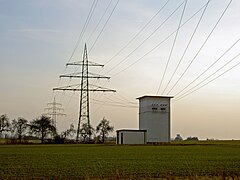
Line leads through a transformer station

Branch in the span to a transformer below

Medium-voltage overhead line with branch to a tower station


Conductor rope

Conductor cables of overhead lines are made of copper , Aldrey and composite cables of steel and aluminum . Due to their lower density, the latter have a larger cross-section and therefore a higher conductance than copper ropes for the same weight and are therefore preferred for high-voltage lines. For voltages above 110 kV alternating voltage , so-called bundle conductors are often used in order to avoid corona phenomena and to increase the natural performance of the line . These consist of several conductor cables connected by spacers and reduce the effective edge field strength to values below 17 kV / cm, from which ionization begins in air. For 220 kV lines, two-bundles are mostly used, for 380 kV lines mostly three or four-bundle conductors are used.
The maximum continuous temperature of the conductor cables due to the current load is 70 ° C to 80 ° C depending on the type of cable and is specified in the standards DIN 48201 and DIN 48204. In the event of a short circuit, the maximum temperature of the conductor cable may briefly rise to 160 ° C to 170 ° C - higher temperatures would weaken the material of the cables under tension. The economical current density with low thermal heating is 0.7 A / mm² to 1 A / mm², with continuous operation with approx. 2 A / mm² to 2.5 A / mm² at an ambient temperature of 30 ° C in summer the maximum permissible continuous operating temperature of the conductors reached, in winter this value is higher. De-icing of power lines in winter called to Abtauschaltungen be used.
A typical conductor cable of a high voltage line (110 kV ) consists of a seven-core steel core with a total cross-sectional area of 60 mm², which is sheathed by a braid of 30 aluminum cores with a total area of 257 mm². With a nominal current of 560 A per line, this results in an output of 107 MVA per three-phase system. With a 380 kV line with 1,300 A per outer conductor, over 850 MVA can be transmitted, whereby the natural output is 600 MW.
In the case of overhead lines for three-phase current, three conductor cables (or three bundle conductors) are tensioned per three-phase system. At certain intervals their position on twisting masts changes to one another and - at different distances to the ground - to the earth. This twisting achieves a symmetrical capacitance in the three-wire system, which is essential for earth fault compensation in so-called quenched networks , among other things .
In some regions near the airport, marker lamps for high-voltage lines are attached to the conductor cables as an obstacle to aviation , such as the Balisor system . Spherical rope markers, also known as aerial warning balls, are used to mark the day .
Earth rope


An earth wire, like conductor ropes, is an electrically conductive rope, which does not carry any electrical voltage, but runs above the current-carrying conductor ropes and is usually attached to the top of the mast in an earthed state . The earth wire is supposed to protect the live conductor ropes from lightning strikes. As a rule, overhead lines with operating voltages above 50 kV are equipped with an earth wire.
A fiber optic cable for data transmission is often embedded in the earth wire. These data transmission capacities are also made available to telecommunications providers by the network operators.
For higher demands on lightning protection , high-voltage lines are sometimes equipped with two earth cables. These are either at the extreme ends of the top traverse, on a V-shaped mast tip or on a separate earth wire traverse. With the one- level arrangement , two earth ropes are required at least whenever there is no top of the mast, as the protected area of a single earth rope is insufficient here.
Isolators

.jpg)
Suspended or standing isolators are used as isolators for voltages up to approx. 50 kV. The former can withstand higher forces, the latter offer additional safety, as the conductor rope falls onto the mast in the event of an insulator break.
The lines on standing insulators also pose a danger to large birds that land or fly off on the crossbar between the insulators and can easily cause earth faults . To avoid this, some lines in the mast area are covered with bird protection fittings , or an additional perch is installed at a safe distance above the upper cross member .
Greater resistance to breakage can be achieved by using two (or more) parallel isolators. Only hanging long rod insulators are used for voltages above 50 kV . Glass or ceramic is usually used as the insulator material. For voltages above 200 kV, chain insulators consisting of two to four long rod insulators are often used. For voltages above 100 kV, insulators made of high-strength plastic are also used (silicone insulators).
In the case of long spans, wind and other mechanical influences can cause undesirable mechanical vibrations in the conductor cable. This can result in mechanical damage to the conductor and the insulators. To dampen these vibrations, Stockbridge vibration absorbers are installed near the suspension points of the overhead line, in close proximity to the isolators .
Distances to high-voltage overhead lines
Overhead lines must maintain certain minimum distances from the ground, traffic routes and buildings in order to prevent inadmissible approaches. The dimensioning of these distances is regulated in EN 50341. This is based on the largest sag that can occur depending on the conductor temperature or ice build-up. The distances required according to EN 50341 are composed of a basic electrical distance D el and a safety distance D s . The basic electrical distance D el represents a fictitious circumference around the conductor cable with the radius D el , within which a rollover can occur even without touching the conductor. The distance to other conductor cables D pp ensures that there is no flashover to other conductor cables of the same or to another cable if cables cross.

| Nominal voltage U n in kV | D el in m | D pp in m |
|---|---|---|
| 10 | 0.15 * | |
| 20th | 0.22 * | |
| 30th | 0.32 * | |
| 110 | 1.00 | 1.15 |
| 220 | 1.70 | 2.00 |
| 380 | 2.80 | 3.20 |
* The values for voltages below 110 kV were not available. As an alternative, the distances to the danger zone from DIN VDE 0105-100 are given.
The distances to be maintained by overhead lines are specified in EN 50341 depending on the type of property:
| Property type | distance to be maintained |
|---|---|
| ground | 5 m + D el |
| Traffic system (upper edge of the road) | 6 m + D el |
| Fixed roofs, slope> 15 ° | 2 m + d el , but at least 3 m |
| Fixed roofs, slope ≤ 15 ° | 4 m + d el , but at least 5 m |
| Other roofs | 10 m + D el |
| Steep slope with no traffic | 2 m + d el , but more than 3 m |
| Climbable trees | 1.5 m + d el , but more than 3 m |
There are also separate specifications for bodies of water. For example, the following distances are specified in shipping regulations for 110 kV lines: 17.5 m for the Elbe, 15 m for the Mittelland Canal, 8 m for subordinate waters.
The distances for carrying out work in the vicinity of live parts are specified in DIN VDE 0105 and in principle also apply to work in the vicinity of overhead lines. The required distances depend on the qualifications of the employees. For electrotechnical laypeople who are not familiar with the dangers associated with electricity, greater distances apply than for electrical specialists or electrotechnically trained persons .
| U n to ... | Distance for electrotechnically trained persons | Distance for electrotechnical laypeople |
|---|---|---|
| 1 kV | 0.5 m | 1.0 m |
| 30 kV | 1.5 m | 3.0 m |
| 110 kV | 2.0 m | 3.0 m |
| 220 kV | 3.0 m | 4.0 m |
| 380 kV | 4.0 m | 5.0 m |
| 500 kV | 8.0 m | |
| 750 kV | 11.0 m | |
| 1000 kV | 14.0 m |
In Germany and Austria it is generally permissible to run overhead lines under viaducts . Such a crossing can be found, for example, at the Brenztalbrücke of the A 7 or the Körschtal viaduct near Esslingen am Neckar. But bridges themselves can also support structures to which overhead lines are attached, such as Storstrømsbroen in Denmark.
mast
Operating parameters
Overhead lines for power transmission are characterized by parameters of the nominal voltage, the natural power and the line impedance . The following table summarizes exemplary guide values for some common voltage levels:
| Power and line impedance | ||||
|---|---|---|---|---|
| Nominal voltage (kV) | Conductor cross section Al / St (mm²) |
Line impedance (Ω) |
natural power (MW) |
thermal limit power (MVA) |
| 10 | 50/8 | 330 | 0.3 | 3 |
| 20th | 120/20 | 335 | 2.7 | 14.2 |
| 110 | 240/40 | 380 | 32 | 123 |
| 220 | 2 240/40 | 276 | 175 | 492 |
| 380 | 4 240/40 | 240 | 602 | 1700 |
| 750 | 4 680/85 | 260 | 2160 | 5980 |
Noise development

In rain , fog , snow or damp weather , there is often a low humming or whirring sound emanating from high-voltage lines. These noises are caused by two effects:
- Hum or hum
- is created by water droplets that adhere to the conductor cables and are stimulated to mechanical vibrations by the frequency of the electrical voltage. If the alternating voltage of the line has a frequency of 50 Hz , the drop will change its shape from the original spherical shape to an elongated shape and back again with every half oscillation , i.e. 100 times per second. As a result, with each half-wave, a greater protrusion arises on the conductor, which triggers an ion wind , which in turn periodically heats the ambient air. Originally it was assumed that the water droplets themselves generate the sound, but this would be far too weak compared to the measured values. The more water droplets adhere to the line, the louder the hum becomes. The volume also depends on the size of the water droplets - larger droplets produce a louder noise. Often the harmonics of the 100 Hz oscillation can also be heard. In countries with a 60 Hz power grid, the frequency of the tones is 120 Hz. Special coatings or surface structures are intended to facilitate water drainage from the conductors or at least keep the droplet size small.
- Higher-frequency noises such as crackling or hissing
- They come from pre-discharges or corona discharges , which also produce ultraviolet radiation and ozone . The sound spectrum is between 500 and 12500 Hz. The cause of the discharges is the high electric field strength on the surface of all live components, which ionizes the surrounding air and thus becomes electrically conductive. High marginal field strengths arise mainly on the sometimes sharp edges of the fittings on a mast between the insulator and the conductor, so the noise can be heard more strongly here than in the tension field between the masts.
- The associated transmission losses and noise emissions increase with the voltage. At voltages above 100 kV, u. a. therefore bundle conductors are used, which reduces the electric field strength on the conductor surface and thus the corona losses and the hissing noises.
- Whistling of the lines in the wind
- It is created by the Kármán vortex street that arises behind the rope around which the flow is flowing.
Telecommunication technology

Overhead line with several trusses

Cable transfer point at the transition from underground cable to overhead line

Overhead line mast with a traverse


In telecommunications technology, an overhead line is a line made of bare wires and routed over telephone poles . The core of the wires is made of steel to safely absorb the tensile forces, for better conductivity they are sheathed with bronze , the surface of which develops a matt green copper patina over time . They are attached to the masts with insulators made of glass, ceramic or plastic. Short circuits between the wires are avoided by maintaining a minimum distance; in Germany the distance between the wires was standardized to 17 cm. A telephone connection (subscriber connection) requires two wires each. Until the late 1960s, overhead telephone lines were common on country and county roads, especially in rural areas. Long-distance lines were run along railway lines. The overhead line ended at so-called transition masts and was continued as an underground cable, e.g. B. in localities and groups of houses that were underground. The transition is formed by the cable transfer point (KÜ), a special cable termination in a weatherproof housing. For lightning protection, it also contains knife-edge fuses between cable and overhead line cores and voltage breakdown fuses between the overhead line cores and the earth potential.
The public telephone network in Germany, which originally consisted of overhead lines, has now been converted to underground cables , and occasionally also overhead cables , as overhead lines are often disrupted by the weather: storms knock over masts, wires break due to the build-up of ice. In Germany and western continental Europe, overhead lines for the purpose of transmitting messages have now almost completely disappeared. The last telephone lines with bare wires in the public telephone network are likely to have been replaced by aerial or underground cables in the old federal states in the second half of the 1970s, in the new federal states around 1999. However, no date can be determined for the dismantling of the last overhead telephone line in the public telephone network in Germany.
Telecommunication lines can still be found occasionally in the BASA telephone network along non-electrified branch lines. These are also increasingly being dismantled with the introduction of GSM-R . In the past, overhead lines existed almost everywhere on almost all railway lines, on main lines often in the form of double rods. In many cases, they were used jointly by the railroad and postal administrations as community poles.
On lines with overhead lines, the line connections of the line block are also routed through it. Special, plastic- insulated block wire is used for this. In the case of overhead line rods with several traverses one above the other, the blockers are placed in the upper positions if possible. If a block connection is switched to non-isolated telecommunication wires in the event of a malfunction, feedback must be maintained due to the reduced security before wire contact .
The decisive factor in replacing overhead lines with cable connections on railway lines was electrification with single-phase alternating current. In principle, overhead lines can remain on direct current railways, but the inductive influence makes parallel telecommunications overhead lines on AC railways unusable.
In other countries, including industrialized countries such as Great Britain, the USA and Japan , large parts of the subscriber lines are still designed as overhead lines. In the last two countries mentioned, this is operationally cheaper in places, since after the natural disasters such as earthquakes or storms that frequently occur there, repairing underground cables is much more expensive than repairing overhead lines.
Overhead lines have an antenna effect and can therefore also capture amateur radio and CB radio . While normal telephone traffic is hardly affected by this, interference can occur on DSL transmission if radio and DSL use the same frequency ranges.
Overhead lines in alarm systems
Until the 1990s, signals were transmitted from manually operated fire alarms in public spaces to the reporting points, in some cases via overhead lines. These were mostly unipolar and often attached to lampposts, suspensions for street lamps or house walls.
More types
Overhead lines
A special form of the overhead line, the overhead lines and bus bars of electric railways; these must be equipped for the extraction of electrical energy by the pantograph of rail vehicles and therefore consist of solid conductors made of a copper alloy.
Fish trap lines

Overhead lines are also occasionally used to feed transmission antennas, especially antennas of very powerful transmitters for long , medium and short wave . A trap line is often used for this. In the case of a trap line, several parallel conductors form a coaxial line with the outer conductors at ground potential . Inside the ring, attached to insulators, runs the high-voltage feed line of the antenna. It is usually also designed as a bundle conductor.
Single wire high voltage supply
In many sparsely populated areas of the world (in Europe e.g. in Iceland) there are single-wire high-voltage supplies for remote houses or hamlets. The ground acts as a "return conductor".
Single-wire waveguide
Single-wire waveguides used to be used in places with unfavorable reception locations (valleys) to broadcast radio programs. The waves propagating along a single overhead line could be received by dipole antennas located near the line ; see Goubau management .
Related constructions
- Antennas (are often designed similar to overhead lines for longer waves)
- Self-radiating transmission mast
- Overhead line
- Busbar
- electric fence
Use of the area under an overhead line

The area under an overhead line can be used for most purposes where there is no risk of objects connected to the ground coming into the vicinity of the conductors or where there is a risk that the conductors will be exposed to the way they are used , Isolators or mast structures can be damaged. However, radio reception under overhead lines can be impaired - especially when receiving signals with frequencies below 10 MHz - when using rod antennas. If it is not possible to move the receiving antenna, then in this case magnetic antennas (frame or ferrite antennas) should be used. When building the area under overhead lines, it should be remembered that ice can build up on the masts and conductor cables in winter and that falling chunks of ice can cause damage to the building.
Security advice
In the vicinity of overhead lines (and also of radio towers , in particular of self-radiating transmitter masts ) it is forbidden and dangerous to let kites or tethered balloons soar, as dangerous currents can flow through the line, especially when wet.
For some time now, aluminized foil balloons have only been allowed to be issued with the ballast weight installed in some countries (USA, A ...) in order to prevent them from escaping, as the thin, gas-tight aluminum layer near a line insulator triggers an arc discharge that burns the balloon and an electric discharge leaves conductive contamination of the insulator, which is why it must be replaced afterwards.
In the case of low-hanging overhead lines, care must be taken when handling long poles or ladders , especially if they are made of electrically conductive material.
Motor vehicles should not be refueled or containers filled with flammable liquids under high-voltage overhead lines.
If a torn conductor of a high voltage line is on the ground, you should not approach it, or move away from it only with triple steps ( step voltage ).
history
The world's first overhead line was built by the physicist Stephen Gray on July 14, 1729 to show that electricity could be transmitted. He used moist hemp cords attached to bean sticks as a ladder. However, there were first practical applications of overhead lines only in the context of telegraphy .
In 1882, the first high-voltage overhead line transmission between Munich and Miesbach was carried out, using direct current with a voltage of 2 kV. The efficiency was 25%. Oskar von Miller and the Frenchman Marcel Deprez were involved in the realization .
In 1891 the first three-phase overhead line was built on the occasion of the international electricity exhibition in Frankfurt / Main between Lauffen am Neckar and Frankfurt am Main . The energy was transported over 176 kilometers at 10 kV, the efficiency was 75 percent.
In 1905 the first overhead line with 50 kV operating voltage went into operation between Moosburg and Munich .
In 1912 the first 110 kV overhead line (between Lauchhammer and Riesa ) and in 1922 the first 220 kV overhead line went into operation. In the 1920s, RWE AG built the first overhead line network for this voltage, which was partially designed for 300 kV ( north-south line ) and which also included the Voerde Rhine overhead line crossing built in 1926 with two 138-meter-high masts. In 1957 the first 380 kV overhead line went into operation in Germany (between the Hoheneck substation and Rommerskirchen).
In the same year, the overhead line crossing of the Strait of Messina went into operation in Italy , the masts of which served as a model for the support masts of Elbe crossing 1 and were the highest overhead line masts in the world until the construction of Elbe crossing 2 in the second half of the 1970s.
From 1967 overhead lines for voltages of 765 kV were built in Russia, the USA and Canada. In 1982 a three-phase current line with 1,150 kV was built in Russia between Elektrostal and the Ekibastus power plant .
In 1999, a 500 kV double line was built in Japan, which is designed for an operating voltage of 1100 kV, the three-phase line Kita-Iwaki .
2003 saw the construction of the highest overhead line masts to date on the Yangtze overhead line crossing in China .
Controversy
When building high-voltage overhead lines, there was and is repeated resistance from residents in densely populated regions in Central Europe and in narrow regions such as mountain valleys.
The opponents of overhead lines apply disadvantages for scenic and visual reasons, because of economic impairment, for example due to the erection of a mast in a field, but also because of impairments due to a supposedly non-existent electromagnetic environmental compatibility . Opponents of overhead lines usually demand underground cabling , which, however, is more expensive than an overhead line and is often physically difficult.
The objective influencing of the residents of an overhead line or an overhead line is given by the electric and magnetic fields, the noise and the landscape.
Even at a small lateral distance from the line and especially in buildings, the electric field is below the limit value of 5 kV / m. The magnetic field depends on the level of the current in the line. It is also at the maximum possible current and directly below the overhead lines below the limit value of 100 µT (precautionary limit value for the population). In a measurement study, a maximum of 5.9 kV / m and 4.6 µT were measured directly under high and extra high voltage overhead lines, and 9.0 kV / m and 52 µT were extrapolated from this for the maximum system utilization. From a distance of 100 to 400 meters, the field strengths that typically occur in households exceed the fields of high-voltage overhead lines.
The 26th Federal Immission Control Ordinance provides for a minimization requirement, which means that potential electrical and magnetic fields should be kept as low as possible during planning.
Medium and high voltage underground cables are often used in urban areas despite the higher transmission losses, higher costs and longer downtimes, as overhead lines often cannot be built there. These are comparatively short distances of a few kilometers.
Records
- Longest span : crossing of Ameralik Fjord, 5376 m, Greenland, from Greenland's first power station, built in 1993
- Longest span in Europe: crossing the Sognefjord near Leikanger , 4597 m, Norway
- Longest span in Germany: Eyachtalquerung Höfen, 1444 m
- Longest overhead line connection: Rio Madeira HVDC (HVDC), Brazil (Rio Madera - SO-Brazil) 2375 km (made in August 2014)
- Formerly longest overhead line: HVDC Inga-Shaba : 1700 km
- Formerly the longest switchable overhead line section in Germany: Wolmirstedt - Lubmin 287.8 km (until the Stendal-West substation is commissioned on October 1, 2009)
- Highest transmission voltage: three-phase line Ekibastus – Kökschetau , 1150 kV
- Highest transmission voltage DC voltage: HVDC Yunnan – Guangdong , ± 800 kV
- Highest overhead line in Europe: preliminary discharge at 2720 m above sea level. M. Switzerland
- Formerly tallest overhead line masts - no longer used as such, but under monument protection: power line crossing of the Strait of Messina 232 m, Sicily
Specialist literature
Reference books
Overhead line technology:
- Friedrich Kießling, Peter Nefzger, Ulf Kaintzyk: Overhead lines. 5th edition. Springer, Heidelberg 2001, ISBN 978-3-642-62673-9
Energy Technology:
- Rene Flosdorff, Günther Hilgarth: Electrical energy distribution. 4th edition. BG Teubner, Stuttgart 1982, ISBN 3-519-36411-5
- Günter Springer: Expertise in electrical engineering . 18th edition. Verl. Europa-Lehrmittel Nourney, Vollmer, Wuppertal 1989, ISBN 3-8085-3018-9
- Wilfried Knies, Klaus Schierack: Electrical systems engineering - power plants, networks, switchgear, protective devices. Carl Hanser, Munich / Vienna 1991, ISBN 3-446-15712-3
Telephony:
- Handbook of telecommunications technology , Volume 7, Part II: Line technology . (PDF) 1973
Technical articles
- Walter Castor: Basics of electrical energy supply. HAAG Library, HAAG Electronic Messgeräte GmbH, Waldbrunn
Web links
- Location of overhead lines on the Open Infrastructure Map (incomplete)
Individual evidence
- ↑ High voltage line. In: Dr. Rüdiger Paschotta, RP-Energie-Lexikon. November 3, 2018, accessed July 28, 2019 .
- ↑ General administrative regulation for the marking of aviation obstacles. Retrieved October 21, 2018 .
- ↑ Air warning ball assembly. Netz Oberösterreich , June 2, 2014, accessed on October 21, 2018 .
- ↑ DIN EN 50341-1: 2013-11 Overhead lines over AC 1 kV - Part 1: General requirements - Common specifications ; German version EN 50341-1: 2012
- ↑ Operating manual. (PDF) (No longer available online.) P. 9 , archived from the original on September 21, 2016 ; accessed on September 21, 2016 . Info: The archive link was inserted automatically and has not yet been checked. Please check the original and archive link according to the instructions and then remove this notice.
- ↑ Operating Instructions . (PDF) p. 16 , accessed on September 21, 2016 .
- ↑ Page no longer available , search in web archives: Transmission behavior of high voltage lines (PDF) including sample calculations, Institute for Energy Supply and High Voltage Technology, University of Hanover, 2009
- ↑ a b http://archiv.ethlife.ethz.ch/articles/tages/Hochspannung.html Richard Brogle: Tanzende Wassertropfen , notification from ETH Zurich in the daily reports section , January 24, 2002, accessed on May 7, 2020
- ↑ a b https://www.hlnug.de/fileadmin/shop/files/Schriften_Laerm_587.pdf P. Sames, M. Goossens: Metrological field studies on corona noise , in Lärmschutz in Hessen , issue 5, page 6f, created i. A. Hessian State Office for Environment and Geology , ISBN 978-3-89026-576-6
- ↑ Objections 140–153 administration.steiermark.at, October 2004, accessed on February 29, 2020.
- ↑ Lucia Probst: "A floor installation is significantly more expensive, it stays that way" bernerzeitung.ch, February 28, 2012, accessed on February 29, 2020.
- ↑ Field pollution from high-voltage lines: overhead lines & underground cables. Federal Office for Radiation Protection, accessed on May 11, 2020 .
- ↑ H.-Peter Neitzke, Julia Osterhoff, Hartmut Voigt, ECOLOG Institute for Social-Ecological Research and Education GmbH: Determination and comparison of the exposure caused by underground cables and high-voltage overhead lines to low-frequency electric and magnetic fields. (PDF) Federal Office for Radiation Protection, September 15, 2010, accessed on May 11, 2020 .
- ↑ https://www.bundestag.de/resource/blob/645096/c353de5ae1027694bd262799c00cf223/WD-8-011-19-pdf-data.pdf High-voltage lines: Individual questions on health hazards and limit values , a publication by the Scientific Services of the German Bundestag , 8 February 2019, accessed May 7, 2020
- ↑ Sonal Patel: A New Record for the Longest Transmission Link October 1, 2014, accessed October 13, 2017.