Clamp circuit (communications engineering)
A clamping circuit is used to add a DC voltage to the AC voltage behind a coupling capacitor .
purpose
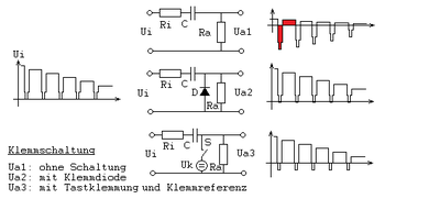
If a mixed voltage is applied to a coupling capacitor , only the alternating voltage component is transmitted up to a lower limit frequency (see Ua1 in the figure). Lower frequencies or DC voltage components are lost. These should either be restored or replaced by a specified voltage. This occurs frequently in communications engineering (for example clamp level for picture tubes in monitors or television receivers on).
functionality
A distinction is mainly made between the passive tip clamping and the active tactile clamping.
The prerequisite for the functioning of a clamping is that the target signal periodically has known DC voltage values and that the period is significantly shorter than the time constant of the high-pass filter of the transmission path.
Tip clamping
If, for example, as shown in the picture, there is an input voltage that periodically contains a fixed reference level, a clamping diode , which acts as a switch, can be clamped to the reference potential, as the coupling capacitor recharges itself again and again. The time constants of R a and C should be as large as possible so that the capacitor discharges only a little during the breaks. Conversely, the time constants of R i and C should be as small as possible so that the coupling capacitor can charge up quickly. The DC component and the terminal polarity can be selected by reversing the polarity of the diode or connecting a voltage (clamping voltage) in series with it. The disadvantage of the tip clamping is that the diode has a forward voltage and that the circuit also reacts to interference voltage peaks.
Tactile clamp
With this, the disadvantages of tip clamping are largely avoided. The desired signal section is scanned by a switch, usually implemented as a semiconductor component (in Fig. S ), and clamping is then forced. The disadvantage is that the circuitry is more complex, since a synchronous control is required to control the sampling switch. The dimensioning is to be carried out as with the tip clamping.
See also
Individual evidence
- ^ M. Koubek: television reception technology . Franzis-Verlag 1969, p. 191.
- ↑ Waveform clamping with Schottky Diodes , Application Bulletin 15, Hewlett-Packard
- ↑ Telefunken Laborbuch , Volume-V, 1971, p. 128
- ^ Heinz Richter : Color television for everyone . Frankhsche Verlagsbuchhandlung, 1967, p. 118.
- ^ Otto Limann: Television technology without ballast . Franzis-Verlag, 1973, ISBN 3-7723-5270-7 , p. 94, p. 242
