Power factor correction filter
An active or passive power factor correction filter ( English Power Factor Correction or English Power Factor Compensation , abbreviated PFC ) is an electrical or electronic circuit including the so-called power factor increases so that it remains in a legal predetermined range. Areas of application include electronic loads with switched-mode power supplies that are connected to the public power grid .
General
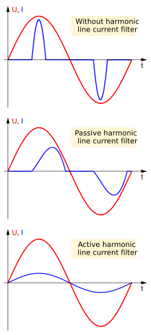
With non-linear loads, i.e. mainly rectifiers with subsequent smoothing in switched-mode power supplies , phase-shifted and non-sinusoidal input currents occur with sinusoidal AC voltage supply . These are made up of a sum of higher-frequency components, i.e. harmonics , which can cause interference in the power supply networks and other electrical devices. In three-phase networks , inadequate filtering of the harmonics can lead to inadmissibly high current loads on the neutral conductor , which is sometimes weaker for cost reasons , as the odd harmonics that can be divided by three add up instead of canceling out each other as in the case of the fundamental on the neutral conductor.
The power factor is described by a value that should be as close to 1 as possible. This is guaranteed by the power factor correction filter. Usual compensation values are in the range around 0.98.
Two variants are common:
- Passive harmonic filters (Passive PFC)
- As a rule, these are chokes with high inductance . Passive filters are easy to manufacture, but they only achieve moderately good results. They are usually only used for small outputs (up to around 200 watts), as their chokes are large and heavy. In addition, there are also special circuit variants that are part of the passive harmonic filters (such as the valley fill circuit ). The filter effect is achieved through a special interconnection of the smoothing capacitors without large filter chokes.
- Active harmonic filters (Active PFC)
- The circuits required for this are more complex, but achieve a very good power factor correction of typically 0.98. A kind of additional switched-mode power supply, which is connected upstream of the actual one, ensures that the current consumed corresponds to the sinusoidal mains voltage. More precisely, the current follows a curve that would be produced by a resistance at the current mains voltage. Thus, if the voltage is not exactly sinusoidal, as it often occurs in power grids, the actual course - not the idealized - of the line voltage is followed.
- Active PFC circuits usually consist of a rectifier with a directly downstream step- up converter , which charges a large capacitor to a voltage above the peak voltage of the AC mains voltage (typically 350–400 V) (also called intermediate circuit voltage ). From this the actual consumer (switched-mode power supply or e.g. electronic ballast for fluorescent lamps ) is supplied.
- Furthermore, an active PFC can compensate for mains voltage fluctuations. Often it is dimensioned in such a way that devices equipped with it can work worldwide on all mains voltages without switching (wide-range input of typically 100 ... 240 V).
- The active PFC generates additional high-frequency interference, which must be suppressed with an upstream passive line filter .
PFC as reactive power compensation
A reactive power compensation , as it is achieved with a simple capacitor in parallel to an inductive load, only effects a phase correction of the current consumption with regard to the fundamental. The goal of bringing the active factor close to one can only be achieved with linear inductive loads.
In the case of non-linear consumers, it is not advisable to specify the active factor related to the fundamental , since here the so-called distortion reactive power is distributed over the harmonics. Examples of such loads are switched-mode power supplies, power supplies with transformers, rectifiers and charging capacitors, arc furnaces , thyristor controllers and dimmers, as well as direct voltage generation for frequency converters .
In addition to reactive power compensation by the PFC, which is connected between the grid and the direct current consumer, there is also parallel compensation. So z. B. a single-phase bridge circuit with disconnectable valves and capacitive load, connected to the mains via a small inductance, can be used as a highly dynamic compensator.
Statutory Regulations
On January 1, 2001, the EMC standard IEC / EN61000 came into force, which defines the regulations on the permissible low-frequency interference spectrum (harmonics) for electronic consumers from 75 watts. For more information, see Electromagnetic Compatibility # Statutory Regulations


