Rectifier
Rectifiers are in the electrical and electronics to convert AC into DC voltage used. In addition to inverters and converters , they form a sub-group of power converters .
In order to combat alternating components (remaining half-waves ), a rectified voltage is usually smoothed .
A rectification is used for example
- to supply direct current-operated electrical consumers from the alternating current network,
- for the connection of distant power grids or the coupling of non-synchronous power grids via high-voltage direct current transmission (HVDC),
- for measuring purposes,
- for applications in communications engineering, e.g. for envelope demodulation .
The rectification is usually uncontrolled by semiconductor diodes . Active electronic components such as B. thyristors allow a controlled rectification by phase control . Field effect transistors ( MOSFETs ) are used in synchronous rectifiers - especially when rectifying small voltages and large currents - and, due to their lower forward voltage, allow greater efficiency than would be possible with semiconductor diodes.
history
In 1873, Frederick Guthrie discovered that a positively charged electroscope would discharge if you brought a grounded, glowing piece of metal near it. If the electroscope is negatively charged, nothing happens, which means that the electric current can only flow in one direction.
In 1874 Karl Ferdinand Braun discovered the directional electrical conduction in certain crystals. He had the crystal rectifier patented in 1899. The coherer as an early form of the diode dates from around the same time .
The Indian scientist Jagadish Chandra Bose was the first to use crystals to detect electromagnetic waves in 1894 . The first practically usable crystal detector made of silicon was developed in 1903 for radio-technical applications by Greenleaf Whittier Pickard , who had it patented in 1906. In the following years, however, lead sulfide was used more frequently because it was cheaper and easier to use.
Thomas Edison rediscovered Guthrie's observation in 1880 while experimenting with incandescent lamps and had the effect patented in 1884 without knowing any possible application. Owen Willans Richardson later described the effect scientifically, which is why it is now called the Edison-Richardson Effect . About twenty years later, John Ambrose Fleming , who was first an employee of Edison and later a scientific advisor to the Marconi Wireless Telegraph Company , realized that the Edison-Richardson effect could be used to detect weak radio signals. He had the first usable application, the tube diode ("Fleming valve") patented in 1904.
All the effects described so far were only suitable for very low currents. However, the increasing spread of electrical energy required powerful rectifiers, because it is preferably generated by alternating current generators. Since the electrical processes in semiconductors were not clarified until around 1950 (after the invention of the bipolar transistor ), various other rectifier principles were used.
Physical principles
Mechanical rectifier
At the beginning of the 20th century, only electromechanical rectifiers were used to convert AC voltage into DC voltage:
- With corresponding converters , an AC motor and a DC generator sit on a common shaft. These converters were often used for voltage transformation and electrical isolation from the network at the same time.
- So-called choppers were used as inverters of direct voltage for subsequent transformation by means of a transformer. They combined a self-oscillating inverter working with switching contacts (e.g. with a Wagner hammer ) and a second set of contacts coupled with it for synchronous rectification. Due to the contact wear, these were designed to be exchangeable (plug-in base).
- Rotating mechanical rectifiers had a wheel with electrical contacts that enabled the AC voltage to be switched over at precise times. The wheel was driven by a synchronous motor, which ensured synchronization between the rotary movement and the change in polarity of the alternating voltage. The construction was supplied with AC voltage from a high-voltage transformer, for example, in order to generate the high DC voltage for electrostatic precipitators. The contact converter was a further development of this principle.
- Until around 1970, the charging current for the accumulators in motor vehicles was generated by direct current alternators with mechanical rectifiers ( commutators ). The invention of powerful semiconductor diodes paved the way for more powerful three-phase alternators.
Disadvantages of mechanical rectification are contact erosion , especially with higher currents, synchronization problems and the limitation to frequencies below around 500 Hz. The great advantage of the vanishingly low forward voltage and correspondingly very low power loss has only recently been achieved again by controlled MOSFET rectifiers .
Electrolytic rectifier
The principle of anodic oxidation , which played a role in the early days of electrical telegraphy and telephony, opened up a possibility of rectification . Two electrodes immersed in an electrolyte can have rectifier-like properties. One electrode must be made of a noble metal, for example platinum , and the other of a metal that forms a thick oxide layer through anodic oxidation, such as niobium . With this arrangement, current can only flow if the anodically oxidizable metal acts as a cathode. These rectifiers are also known as wet rectifiers or electrolytic rectifiers and could be used up to voltages of around 300 V. The main disadvantages - positional sensitivity and toxic or corrosive vapors - limited the number of applications.
Mercury vapor rectifier
A further development was the mercury vapor rectifier, which could also be used for larger outputs, for example to feed an overhead line of a tram. It consists of a glass bulb, at the lower end of which there is a cathode with a mercury supply (pond cathode). The glass bulb on which the mercury condenses again arches above it . Arms with graphite electrodes as anodes are fused to the sides . Electrons can only flow from the pond cathode to the graphite electrodes. To do this, the ignition voltage of the gas discharge must be achieved, and UV light is generated as a side effect .
Dry rectifier
Plate rectifier

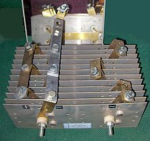
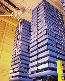
A few decades later, the first semiconductor rectifiers such as selenium rectifiers and copper oxide rectifiers were invented. Since no liquids were used, they were also referred to as dry rectifiers . They consist of a metal plate on which a layer of selenium or copper oxide is applied on the top with tin and a contact spring. The plate size of a selenium rectifier is between one square millimeter and over 100 square centimeters, depending on the current strength. The maximum permissible reverse voltage of such a selenium rectifier plate is only 15 to 50 V , the forward voltage is relatively high at 0.7 to 1.5 V; the copper oxide rectifier has a lower forward voltage, but also a lower reverse voltage of only approx. 10 V. In order to rectify higher voltages, the plates were stacked, i.e. connected in series . Balancing is not required. The number of plates determines the maximum reverse voltage. So-called selenium rods contained a large number of small selenium rectifier disks and were used until the 1970s, among other things, to rectify the anode voltage of picture tubes in black and white televisions. They had blocking voltages up to over 20 kV; Due to the large number of individual elements, the forward voltage was also correspondingly high.
Because of the typical horseradish or garlic-like smell when a selenium rectifier is overloaded, the word "rectifier" was often pronounced as "it smells the same" in technical jargon.
Tip diodes
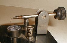
At the beginning of the 20th century, detector crystals made of galena or pyrite were mainly used in detector receivers - a semiconductor - metal transition consisting of a semiconductor crystal and a tactile metal tip, with which suitable points for demodulating AM broadcasts were sought. This mechanically very sensitive and ineffective experimental setup was very quickly replaced by the rapidly advancing development of the electron tube, which enabled circuits that could amplify and rectify at the same time ( Audion ).
Disadvantages are the low blocking voltages of around 15 V and, above all, the low ratio of blocking resistance to forward resistance, which is just over 1 and no longer meets today's standards.
Later, tip diodes based on germanium were manufactured on a large scale, the purpose of which was still the rectification of high frequencies down to the centimeter wave range.
Modern semiconductor rectifiers
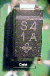
The breakthrough in the development of rectifiers only came after research into the pn junction following the invention of the bipolar transistor in 1947 and the manufacture of flat diodes by means of diffusion or epitaxy .
Was used over a longer period germanium - diodes until later silicon diodes were developed to a higher temperature resistance is associated.
The Schottky diodes , which had been known for a long time, were further developed in order to be able to use them as rectifiers for large currents and low voltages. Their characteristics are the low forward voltage, the low reverse voltage and the relatively high residual current. In this regard, they are comparable to germanium diodes, but have no memory effect and can therefore be used at very high frequencies.
In order to achieve high blocking voltages with short storage times, silicon carbide diodes are increasingly being used for rectification in switched-mode power supplies with higher voltages.
Features of today's semiconductor diodes include the low threshold voltage of well below one volt (germanium and Schottky diodes typically 0.3-0.4 V, silicon diodes 0.6 V), the large ratio of flow to reverse current and the very small design .
Switching power supplies , DC voltage converters and frequency converters only became operationally safe and maintenance-free after the invention of semiconductor diodes.
The reverse voltages of diode rectifiers are between 50 and 1500 V. Higher voltages can be achieved by connecting them in series.
Rectifier diodes of types 1N4001 to 1N4007 (reverse voltage from 50 to 1000 V) for currents up to 1 A and rectifier diodes of types 1N5400 to 1N5408 for currents up to 3 A are widely used rectifier diodes for small currents in the low frequency range.
A disadvantage compared to historical rectifier types is the sensitivity to overload. The reason is the low mass of the crystal. This is why the crystal temperature rises after a very short time (a few milliseconds) in the event of an overcurrent so that the PN layer is irreversibly destroyed. If the reverse voltage is exceeded, only a few types of diodes are able to prevent local overheating through a controlled breakdown ( avalanche diodes ).
Tube diodes
A tube diode or vacuum diode is an electron tube with a heated cathode and one or two (rarely more than one) anode (s). In the early days of broadcast technology, tube diodes were the standard component in tube receivers for rectifying the supply voltage and demodulating the amplitude-modulated signal. Disadvantages are the voluminous and fragile glass housing, the necessary heating power of the cathode and the high forward voltage of around 40 V with currents around 100 mA. In contrast, the high permitted blocking voltages of up to over 100 kV and the extremely high blocking resistance are unmatched.
Glow rectifier
At the end of the 1920s, experiments were also carried out with rectifiers based on glow discharges and special designs of glow lamps . The process is similar to that of the tube diode, but the tube is filled with a gas and the cathode is not heated. The rectifier effect is based on an asymmetrical shaping of the two discharge electrodes or on electrode coatings to reduce the cathode drop. The glow rectifier was unable to establish itself because of its very poor ratio of forward to reverse current (<100: 1), the low maximum current and the incomparably high forward voltage of around 70 V; the use of capacitors for voltage smoothing increased the reverse current even more.
Rectifier circuits
Uncontrolled rectifier
In these circuits only diodes are used, the conductivity of which depends on the polarity of the applied voltage:
- If the cathode is more negative than the anode and the necessary lock voltage (about 0.6 V for silicon) is exceeded, the diode conducts.
- If the sign is reversed, the diode blocks as long as the breakdown voltage is not exceeded.
In both cases the current must be limited, otherwise the diode will be destroyed. Some typical rectifier circuits are outlined below, the technical abbreviation is given in brackets.
Half-wave rectifier (E1) (E1U); also single-pulse midpoint circuit (M1U)
In the case of an uncontrolled half- wave rectifier (also single arm circuit), only one half- wave of the AC voltage is rectified, the other is not used. During the half cycle in which the diode is operated in the forward direction, voltage is present at the output, in the second half cycle the diode blocks. Disadvantages are the comparatively large residual ripple on the DC voltage side, the poor efficiency and the asymmetrical loading of the AC voltage source. As a result, the feeding transformer is magnetized because the current only flows through it in one direction, which is why it must be designed for one-way rectification ( air gap ). Such a rectifier only needs a single diode for this. As a rule, the pulsating DC voltage still has to be smoothed . The ripple has the frequency of the input voltage.
Half-wave rectification comes from a time when rectifiers were still very expensive. Today they can only be found in flyback converters or for generating auxiliary voltages when only very little power is required. Otherwise, one-way rectification is considered obsolete. Black-and-white television sets had a one-way high-voltage rectifier to generate the picture tube anode voltage from the flyback pulses of the flyback transformer. All-current tube radios and televisions had a half - wave rectifier made of selenium, later made of silicon , to rectify the mains and generate the anode voltage . A network pole was used as the ground potential; the tubular heaters operated directly on the grid were connected in series .
Bridge rectifier (B2) (B2U)
The standard rectifier for single-phase alternating current is the bridge rectifier , also called Graetz circuit, Graetz bridge or two-pulse bridge circuit. The namesake is the German physicist Leo Graetz . The circuit is formed by four diodes: The AC voltage on the left, which comes directly from a transformer , for example , is converted into a pulsating DC voltage (shown on the right).
Since this is a two-way rectification, the half-oscillations of the alternating voltage in the direct current circuit at consumer R appear equally polarized. Without a smoothing capacitor, the rms value of the voltage remains approximately the same. In contrast to other types of rectifier, in this rectifier circuit the reverse voltage of the rectifier diodes only needs to be as high as the peak voltage of the alternating voltage. For safety reasons, however, you choose a slightly higher value (for mains rectifiers on the 230 volt network, for example, over 400 V).
The ripple has twice the frequency of the input voltage; The subsequent filter effort is reduced by halving the period duration.
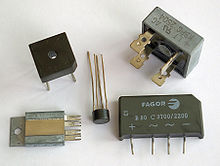
Bridge rectifiers for alternating and three-phase current are often offered as diodes that are already interconnected in a common housing. Versions for higher currents contain a cooling surface and a hole for mounting on a heat sink .
Midpoint rectifier (M2)
With the midpoint rectifier, both half oscillations of the AC voltage are also rectified. However, this requires a transformer with a center tap, which at the same time forms a pole of the rectified output voltage.
The advantages of this mid- point connection are that only two diodes D 1 and D 2 can be used and that the voltage is only reduced by one diode forward voltage . The disadvantage is that it requires a special, larger-sized transformer, since only half of the copper ever contributes to the current flow. With a given copper volume, each half of the secondary winding has roughly twice the internal resistance due to the thinner wire (there must be space for twice the number of turns), which is included in the power loss ( ).
It should also be noted that the reverse voltage of the diodes must be at least twice the output voltage. While one diode blocks and the other conducts, the full transformer voltage of both winding halves is applied to the blocked one.
The ripple has twice the frequency of the input voltage, which, analogous to the bridge circuit, reduces the subsequent filter effort compared to half-wave rectification. The circuit is mainly used at low voltages (below 10 V) and with switched-mode power supplies, as the advantages outweigh the disadvantages. In earlier times, the midpoint circuit was often used in tube devices to generate the anode voltage, since it only required an expensive rectifier unit using duo diodes, rectifier tubes with two anodes and a common cathode or multi-anode mercury vapor rectifiers.
Today double diodes (silicon or Schottky diodes) with a common cathode are often used. They consist of a chip that contains two diodes and the back of which, as a common cathode, is soldered to a cooling lug.
Rectifier for three-phase alternating current
For average outputs of a few kilowatts upwards, the three-phase alternating voltage from the power grid is rectified because the ripple voltage on the direct voltage side is then lower and there is little effort to smooth the direct voltage.
Three-phase rectifiers are used in electrical power engineering such as trams , which are mostly operated with direct voltages of 500–750 V; no smoothing is required. It is also used in today's common three-phase alternators in motor vehicles . The smoothing is done by the starter battery .
Before the time of the semiconductor rectifiers , multiphase mercury vapor rectifiers were also manufactured , which were characterized by a common pond cathode and several anodes protruding upwards.
Rectifier circuits for voltage multiplication
Special rectifier circuits are used to multiply the voltage. Combinations of diodes and capacitors are connected in such a way that an applied alternating voltage results in a multiplied direct voltage. Typical circuits are the voltage doubler , the high-voltage cascade and the Greinacher circuit . These circuits are used, among other things, in television receivers with picture tubes to generate the anode voltage in the range from 18 to 27 kV.
Controllable rectifiers
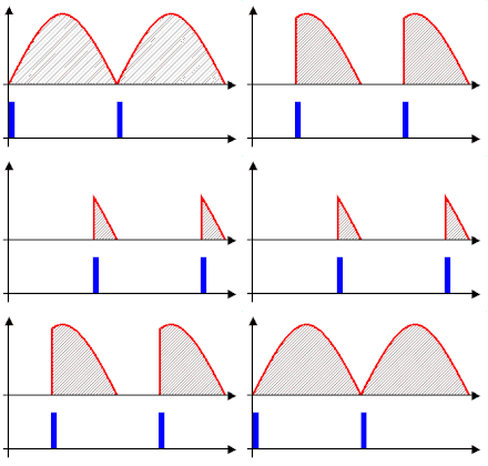
All rectifiers described so far are uncontrolled . The switching process takes place without additional control electronics, only due to the sign of the electrical voltages applied to the diodes. Controllable rectifiers are used in the field of energy and drive technology. They not only enable rectification, but also power control through phase control , because with these components you can specify the point in time from which the rectifier becomes electrically conductive - it insulates beforehand.
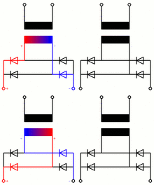
In the picture on the right, the trigger pulse of the thyristors is shown below as a blue rectangle. After the control pulse has expired, the current flow (shown in red) continues until the next zero crossing. By shifting the switch-on time, the energy (gray area) that flows to the consumer can be changed. Areas of application are, for example, the speed control of direct current and universal motors in industrial systems or small devices such as drilling machines, in modern electric locomotives for charging the direct voltage intermediate circuit and in systems for high-voltage direct current transmission . Controlled rectifiers in converters enable very effective frequency and power control of three-phase motors in rolling mills , electric locomotives and washing machines .
In the past, grid-controlled mercury vapor rectifiers such as thyratrons and ignitrons , which are large, expensive and lossy, were used for this purpose . Today thyristors, insulated gate bipolar transistors (IGBT) and in some cases power MOSFETs are used, which require significantly less cooling.
There are also so-called GTO thyristors that allow a valve to be blocked by a pulse. However, these have poorer electrical values and are increasingly being replaced by IGBT.
If a bridge rectifier has fully controllable branches, four-quadrant operation is possible with it, i.e. In other words, with appropriate control, it can supply energy from the alternating current side to the direct current side and vice versa. The corresponding circuit in the form of an H-bridge is called a four-quadrant controller and is used, among other things, in inverters to generate an alternating voltage from a direct voltage.
The controllable rectifiers are divided into several circuit topologies, including B2HZ, B2HK, B2C and B6C rectifiers. The Vienna rectifier is a controllable rectifier circuit with a particularly low harmonic component .
In addition, a controlled rectifier is important in measurement technology , for example in the AC voltage bridge .
Synchronous rectifier

The rectification of very low voltages is problematic because there are no uncontrolled diodes with lock voltages below 0.2 V ( Schottky diode ). Low voltages cannot be rectified at all, with higher voltages there are side effects:
- With envelope demodulators , the demodulated voltage is distorted.
- The efficiency drops considerably at low voltages, and the rectifier becomes hot at higher currents.
This is why powerful synchronous rectifiers are used in switch-mode power supplies with low output voltage.
In this type of rectifier, no components are used that by themselves only allow current to flow in one direction; Instead, MOSFETs are used , which are controlled by control electronics in such a way that they act like semiconductor diodes with a very low forward voltage.
Example: Processors since around the year 2000 require operating voltages of less than 2 V, mobile processors meanwhile less than 1 V. This power is generated in the laptop from 19 V by synchronous converters that use MOSFET rectifiers . Because the forward voltage drop in these components is only a few tens of millivolts, these rectifiers have an efficiency of well over 90 percent and can be implemented without active cooling.
In the circuit diagram shown on the right as part of a switching regulator, the AC voltage is transformed to the required voltage level via a transformer on the left, rectified via the two MOSFETs and the output voltage U 0 is smoothed using coil L and capacitor C. The MOS-FETs are controlled by the same controller circuit that also generates the input frequency; thus the timing of the MOS-FET control is easy. The controller circuit is missing in the circuit diagram for reasons of clarity.
Synchronous rectifiers for low currents can be found in chopper amplifiers , auto-zero amplifiers and lock-in amplifiers .
smoothing

Each rectifier turns the original voltage waveform (often sinusoidal) into a periodically fluctuating DC voltage; that is, an alternating voltage component remains. However, many consumers (for example electronic devices such as computers) require very constant DC voltages, which is why the fluctuations must be compensated. This process is known as smoothing. In the first step, the smoothing is usually carried out using a capacitor with sufficient capacity connected in parallel to the consumer . This capacitor is charged by short current pulses, which start when the rectifier output exceeds the charging voltage of the capacitor and which can assume considerable instantaneous values due to the low current flow angle . Alternatively, the smoothing can also be done by inductivities in series with the consumer, whereby the current flow through the rectifier becomes more uniform. The alternating component remaining after smoothing, also called ripple voltage or residual ripple , can be further reduced by downstream filter elements . Filters for smoothing are low-pass filters .
Further smoothing takes place with a voltage control that compensates for fluctuations in the output voltage. This electronic stabilization almost completely eliminates the residual ripple of the output voltage, which means that even high demands on the quality of the DC voltage (e.g. in laboratory power supplies ) can be satisfied.
The effort for smoothing decreases with increasing frequency of the AC voltage, which is why switched-mode power supplies are used more and more frequently ; they work with frequencies well above the mains frequency (e.g. over 40 kHz) and often replace traditional power supply concepts that still work with inefficient series regulators . For the highest demands, however, longitudinal regulation is still an option. Possibly. it is also combined with switching power supplies, which enables better efficiency. Very powerful rectifiers are always operated with three-phase alternating current, because a total power that does not change over time can be called up from the network; the DC output voltage when using a twelve-pulse rectifier often has a sufficiently low ripple voltage even without smoothing.
In older power supply units for electron tubes , filter chokes (e.g. in the form of the field coil of the device loudspeaker) were used. However, inductors are heavy and expensive, which is why they should be avoided whenever possible. These two disadvantages disappear with increasing operating frequency, which is why the use of inductances is the rule in switched-mode power supplies : Pi filters (two shunt capacitors, a series inductance in between) filter high-frequency components.
Rectifiers in measurement technology
Precision rectification
In electrical measurement technology and in analog audio technology , precise rectifiers are required for small voltages and small currents. They are not used to supply power to electronic assemblies, but to process measurement signals .
Phase sensitive rectification
In contrast to simple uncontrolled rectification, the sign of the output voltage can be reversed for AC voltage measurement technology in the case of a rectification that takes place synchronously with an external process.
Peak rectification
If the voltage is constantly changing, its maximum value or, depending on the version, its minimum value can be recorded, stored and kept ready for further processing. This enables both peak value measurement and the recording of extraordinary events.
Rectifiers in communications engineering
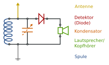
Rectifiers are used in communications engineering for the detection or demodulation of high-frequency signals. A simple example is the envelope rectification of amplitude-modulated signals in detector-receivers . It is shown in the circuit diagram opposite.
The coil and the variable capacitor represent an oscillating circuit that is tuned to the desired high- frequency carrier frequency . The received voltage, the amplitude of which fluctuates depending on the useful signal, is rectified via the diode, which means that the envelope curve of the useful signal is applied to the headphones as a voltage curve - the higher frequency components of the transmission frequency are suppressed by the inductance of the headphones.
This type of receiver is not particularly sensitive and is only suitable for receiving close and strong transmitters. The materials for the diode used to consist of lead luster or pyrite, among other things, and were contacted by a fine metal tip (which is more like a Schottky diode ), whereby a low-capacitance rectifying effect was achieved. Germanium diodes were later used for this .
The underlying principle is also used in today's radio receivers when receiving amplitude-modulated signals.
Rectifier as a non-linear circuit
All rectifiers are non-linear circuits that cause a non-sinusoidal current curve on the DC voltage side with a sinusoidal voltage curve in power supplies. The non-linearity is due to the non-linear absolute value function and the effects of the smoothing on the DC voltage side.
The current on the AC voltage side is made up of several frequency components, so-called harmonics , which can cause disturbances in AC voltage networks. To keep these harmonics small, have power supplies with rectifiers of certain services at a power factor correction feature to minimize the distortion power. This is a special form of filtering that simulates the desired sinusoidal current curve on the alternating current side.
In addition, in rectifiers, as in all non-linear circuits, a special form of reactive power occurs, which is inconsistently referred to in the literature as distortion reactive power or distortion power and has a similar effect to reactive power. In contrast to reactive power, which is also called displacement reactive power and is characterized by a certain phase shift between voltage and current in the fundamental oscillation , this is a form of reactive power that is caused by strong harmonics that arise from the usually small current flow angle . This distortion reactive power, like the displacement reactive power, loads the lines and is undesirable because it does not do any work on the consumer.
On January 1, 2001, an EMC standard came into force that stipulates regulations on the permissible low-frequency interference spectrum (harmonics) for electronic consumers from 75 watts.
Others
- The largest mercury vapor rectifiers ever used were in the high-voltage direct current transmission system Nelson-River-Bipol 1. They had a reverse voltage of 150 kV and a maximum forward current of 1800 A. In the mid-1990s they were replaced by controlled rectifiers based on thyristors.
- Is dipped into dilute sulfuric acid , a platinum electrode and a niobium electrode and this creates a voltage , so only current can flow when the niobium electrode, the cathode is. One speaks here of an electrolytic rectifier . Such rectifiers can also be implemented with other electrolytes and metals . It is important that an electrode is made of metal with a high tendency to passivation, such as niobium, tantalum or aluminum .
- With Schottky diodes , rectifiers with a lower forward voltage can be built than with conventional diodes. The forward voltage or forward voltage describes the voltage drop across the diode in the conductive state and is undesirable for rectifiers. Schottky diodes are mainly used in switched-mode power supplies.
- High-voltage rectifiers, such as those used in high-voltage laboratories, tube televisions , laser printers for applying the toner or high-voltage direct current transmissions , consist of a series connection of conventional diodes. This is necessary because silicon diodes have a maximum reverse voltage of only a few kilovolts and if this voltage is exceeded, breakdown occurs. It is not possible to manufacture semiconductor components with blocking voltages of more than a few kilovolts.
literature
- Manfred Seifart: Analog circuits. 6th edition, Verlag Technik, Berlin 2003, ISBN 3-341-01298-2 .
- Ulrich Tietze, Christoph Schenk: Semiconductor circuit technology. 12th edition, Springer, Berlin 2002, ISBN 3-540-42849-6 .
- Otmar Kilgenstein: Switching power supplies in practice. 3rd edition, Vogel, Würzburg 1992, ISBN 3-8023-1436-0 .
- Ulrich Nicolai, Tobias Reimann, Jürgen Petzoldt, Josef Lutz: Application manual IGBT and MOSFET power modules . Isle, Ilmenau 1998, ISBN 3-932633-24-5 .
Web links
- Synchronous rectifier without diodes: Precision and measuring rectifiers
- Smoothing and filter members
- Mercury vapor rectifier
- Mercury vapor rectifier in action
- Interactive Java simulation of a rectifier bridge circuit
Individual evidence
- ^ Historical lecture on Karl Braun ( Memento from February 11, 2006 in the Internet Archive )
- ↑ diode . Encyclobeamia.solarbotics.net. Archived from the original on April 26, 2006. Retrieved on August 6, 2010.
- ^ DT Emerson: The work of Jagadish Chandra Bose: 100 years of mm wave research . In: IEEE Transactions on Microwave Theory and Techniques . 45, No. 12, December 1997, pp. 2267-2273. bibcode : 1997ITMTT..45.2267E . doi : 10.1109 / 22.643830 . Retrieved January 19, 2010.
- ^ Tapan K. Sarkar: History of wireless . John Wiley and Sons, USA 2006, ISBN 0-471-71814-9 , pp. 94, 291-308.
- ↑ [US patent 836531]
- ^ Road to the Transistor . Jmargolin.com. Retrieved September 22, 2008.
- ↑ Alexander Goldstein: The theory of the contact converter with switching chokes. Diss. Techn. Knowledge ETH Zurich, 1948, e-collection.ethbib.ethz.ch .
- ^ Hermann Goetsch: Textbook of telecommunications technology . 7th edition. R. Oldenbourg, 1938.
- ↑ 1N4001… 1N4007 1.0A rectifier. (PDF; 49 kB) Diodes , February 2, 2009, accessed on July 8, 2013 (English).
- ↑ 1N5400 thru 1N5408 Axial-Lead Standard Recovery Rectifiers. (PDF; 115 kB) ON Semiconductor , May 28, 2008, accessed on July 9, 2013 (English).
- ↑ Nentwig, Geffcken, Richter: The glow tube in technology. German Literary Institute J. Schneider, Berlin-Tempelhof 1939, p. 110 ff.
- ↑ JW Kolar, H. Ertl, FC Zach: Design and Experimental Investigation of a Three-Phase High Power Density High Efficiency Unity Power Factor PWM (Vienna) Rectifier Employing a Novel Integrated Power Semiconductor Module. In: Proceedings of the 11th IEEE Applied Power Electronics Conference. San Jose (CA), USA, March 3-7, 1998, Issue 2, pp. 514-523.
