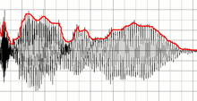
Envelope demodulator
An envelope demodulator , also known as an envelope detector or incoherent demodulator , is a demodulator for amplitude-modulated signals . The first wireless radio receivers, the detector receivers, were thus implemented in communications technology.
technical realization
In the simplest case, an envelope demodulator is implemented using a diode as a rectifier for the input signal. This allows only one polarity of the high-frequency received signal to pass, so that only the upper half of the high-frequency oscillations remain. This is followed by a low-pass filter to remove the high-frequency carrier signal . The result is the original modulation signal , such as speech , music or Morse code . The signal (red curve) is only superimposed by a direct voltage (the mean level of the high frequency), which can be removed by a subsequent coupling capacitor.
The function of the diode can be illustrated by the following thought experiment: If the received signal were sent directly to the low-pass filter, positive and negative amplitude fluctuations would cancel each other out (see picture). The result would be 0 - you wouldn't hear anything.
The crystal detector developed by HHC Dunwoody in 1906 for radio receivers (rectifiers made from a natural mineral) in combination with a downstream capacitor as a low-pass filter replaced the coherer as a pure detector for surrounding high-frequency signals, which made sound (modulation) reception possible. This simple circuit has some disadvantages:
- Signal amplitudes below the threshold voltage of a few 100 mV cannot be rectified
- Signals with higher amplitudes are reproduced in a distorted manner because the threshold voltage is not a fixed fraction of the rectified voltage
- The signal source (usually an oscillating circuit ) is loaded, which is why the quality factor and resonance voltage are reduced.
Improved circuits
These disadvantages can be avoided by using active components that require additional energy but relieve the signal source:
- In the case of cathode rectifiers , an amplifier supplies the required energy, and there is no disturbing threshold voltage.
- In a peak voltage rectifier, a comparator amplifies the input voltage so much that the threshold voltage is no longer relevant.
Therefore, amplitudes of a few millivolts can be rectified without distortion. The maximum frequency is around 10 MHz.
The superimposed DC voltage signal of the demodulator is often used for gain control and to display the field strength. The envelope curve demodulation of the intermediate frequency has mostly been replaced today by synchronous demodulation and partly by fully digital signal processing of the RF input signal.
Envelope detectors are also found, among other things, where a low-frequency useful signal has to be isolated from a higher-frequency carrier signal (e.g. in synthesizers and analysis devices). Today these detectors are implemented as an integrated circuit using a digital signal processor .
Envelope demodulation was used at the time of the analog telephone network to evaluate the inaudible counting pulses.
Demarcation
Envelope demodulators are only suitable for AM with a degree of modulation m <1. The reason for this is that with double-sideband AM the envelope curve with vector addition corresponds - to a certain extent randomly - to the modulating low frequency. If a sideband is missing or, as with SSB, the carrier frequency is too weak, the envelope curve demodulation generates intolerable distortions, whereas a synchronous demodulator still delivers a perfect signal.
literature
- Jens Johann: Modulation method. Basics of analog and digital transmission systems. Springer Verlag, Berlin / Heidelberg 1992, ISBN 3-540-55769-5 .
- Hermann Weidenfeller: Basics of communication technology . Springer Fachmedien, Wiesbaden 2002, ISBN 3-519-06265-8 .
- Rainer Geißler, Werner Kammerloher, Hans Werner Schneider: Calculation and design methods for high frequency technology 1 . Friedrich Vieweg & Sohn Verlag, Wiesbaden 1993, ISBN 3-528-04749-6 .
- Martin Meyer: communication technology. Modern messaging concepts. 2nd Edition. Friedrich Vieweg & Sohn Verlagsgesellschaft, Wiesbaden 2002, ISBN 3-528-13865-3 .
- Martin Werner: communications engineering . An introduction to all courses. 7th edition. Vieweg + Teubner Verlag, Wiesbaden 2010, ISBN 978-3-8348-0905-6 .
- Rudolf Elsner: Message Theory . The transmission channel, Springer Fachmedien, Wiesbaden 1977, ISBN 3-519-06104-X .
- Otger Neufang: Lexicon of Electronics . Friedrich Vieweg & Sohn Verlagsgesellschaft, Wiesbaden 2002, ISBN 3-528-04099-8 .
See also
Individual evidence
- ↑ Product page LT1016 with a link to the datasheet
- ↑ Transmission of the counting impulses on the telephone
Web links
- Amplitude Modulation (accessed September 7, 2017)
- Digital demodulation and evaluation (accessed on September 7, 2017)
- AM Demodulator (accessed September 7, 2017)
- Analog modulation methods and broadcast technology (accessed on September 7, 2017)
- Digital modulations (accessed September 7, 2017)


