Current flow angle
The conduction angle is a term used in electrical engineering and particularly referred to at mains voltage - consumers , the period during which a current flows periodically, if it is not during the entire period of the AC voltage flows. In analogy to the phase shift angle , this time span is specified as the current flow angle. It is used, for example, in explaining rectifier and thyristor circuits .
Information, requirements
Is a stream of a time until a time point is turned on (at synchronous network repetition), then at a period duration is of the mains voltage, the current flow angle defined by the phase angle by
- .
In the case of single-phase alternating current, it can in principle be 0 ... 180 °, although the limit areas cannot easily be implemented with thyristors in terms of circuitry. Depending on the circuit, the current can be periodic after 180 °. In this case, an angle of 180 ° means non-discontinuous operation.
Current conduction angle <180 ° means an interruption of the current. They occur with non-linear consumers. These include rectifiers, dimmers, thyristor controllers or gas discharge lamps.
Strictly speaking, one would still have to specify the threshold (current strength) from which one defines “current flows”. This is not defined uniformly; For most applications, the point in time of the transition from reverse current to forward current or vice versa can be specified with sufficient precision for the current flow angle.
With the same power to the load current loaded with low conduction angle lines or transformers much stronger than current with sinusoidal shape, which is why a possible major aims conduction angle. On the other hand, one wants to achieve a low residual ripple in rectifier circuits , for which purpose a low current flow angle is aimed for. In the second case, the product of consumer resistance and capacity is chosen as large as possible ( = 10 ms in a 50 Hz network).
Examples
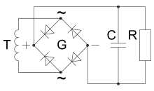
- Rectifier with a connected smoothing capacitor
- Since the capacitor can only be recharged if the instantaneous voltage of the sinusoidal input voltage (mains voltage or secondary voltage of a transformer) is greater than the capacitor voltage, the entire power must be drawn from the network in this short time. So the current in the transformer and rectifier is very high for a short time and zero for the rest of the time.
- In the picture for the voltage curve, the associated current conduction angle is marked with ; there it is approx. 30 °; Current only flows for about a sixth of the time, which then has a peak value far more than six times the equivalent value at the consumer.
- Larger losses occur on the input side, since the rms value of the current exceeds its rectified value the more pronounced the current peak becomes. For given ohmic resistances (network and, if applicable, transformer internal resistance), the power loss increases with the square of the effective current value.
- There are harmonics and thus distortion reactive power . This can be remedied by a power factor correction (PFC) or in the simplest case a choke / coil before or after the rectifier.
- Thyristor controller or triac controller or dimmer ( phase control )
- The adjustment of the current flow angle is used here for power control. Excessive peak currents are avoided with chokes.
See also
- Crest factor
- Duty cycle (for pulsating direct current)
Individual evidence
- ^ Karl Küpfmüller: Introduction to Theoretical Electrical Engineering , 1984
- ^ Johann Siegl: Circuit technology - analog and mixed analog-digital , 2005
- ↑ Wolfgang Böge, Wilfried Plassmann: Vieweg Handbook Electrical Engineering , 2007
- ↑ Herbert Bernstein: Workbook Mechatronik , 2007
- ^ Joachim Specovius: Basic course in power electronics , 2009


