DC-DC converter
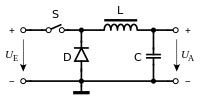
A DC-DC converter , and DC-DC converter , called english DC-DC Converter , refers to an electrical circuit that a voltage supplied at the input DC voltage is converted into a DC voltage with higher, lower or inverted voltage level. The implementation takes place with the help of a periodically working electronic switch and one or more energy stores. DC voltage converters are among the self- commutated power converters . In the field of electrical power engineering , they are also referred to as direct current controllers .
The inductance (inductive converter) used to temporarily store the energy consists of a coil or a converter transformer. In contrast, converters with capacitive storage ( capacitive converter ) are called charge pumps . Charge pumps are used when either - as in integrated circuits - inductances are not available, or when so little output power is required that the use of expensive coils is not worthwhile compared to cheap capacitors.
Devices that convert a direct voltage into an alternating voltage , on the other hand, are called inverters ; together with other types of converters , both belong to the group of converters .
Applications
DC voltage converters are part of switched-mode power supplies with which loads such as PC power supplies , notebooks , mobile phones , small motors, hi-fi devices, etc. v. m. operate. The advantages over linear power supplies are better efficiency and less heat generation. Above all, the former plays a major role in converting a battery voltage , since the service life of the battery is much longer with a switched-mode power supply: with a linear voltage regulator or a series resistor, however, the power dropping across the series resistor is converted into waste heat. In contrast , the switching losses occurring in the switched-mode power supply are significantly lower.
In addition to its function as a voltage converter, a clocked voltage regulator also serves as a filter, in order to keep the negative influence on the power grid (so-called grid feedback ) as low as possible , especially in high-performance applications . One example is active power factor correction (PFC).
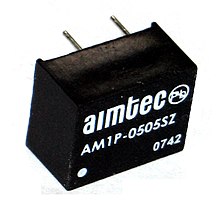
DC-DC converters are also offered as fully encapsulated converter modules, some of which are intended for direct assembly on printed circuit boards . The output voltage can be smaller, equal to or larger than the input voltage, depending on the design. The best known are the assemblies that translate a low voltage to a galvanically isolated low voltage. The encapsulated DC-DC converters are offered for insulation voltages from 1.5 kV to over 3 kV and are used to power small consumers in DC voltage networks such as B. to 24 V in industrial plants or to 48 V in telecommunications or the field of electronic assemblies, for example 5 V for digital circuits or ± 15 V for operating operational amplifiers .
DC voltage converters for high output voltages (e.g. electronic flash units) are also called transverters.
In electrical power engineering and drive technology , direct current converters are referred to as direct current converters. The differences primarily concern the use and the performance range. As a switch in the field of energy technology as valves referred to here are power MOSFET , IGBTs and thyristors used. DC choppers are also used in this field of application as a combination in the form of a two- or four-quadrant chopper . Based on this terminology, the simple DC chopper is called a single-quadrant chopper.
Topologies (basic circuits)
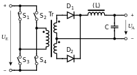
DC voltage converters are classified according to different criteria and divided into different topologies. The assignment of the individual topologies to the main groups of the forward converter principle, flyback converter principle and resonance converter principle is not standardized in the literature.
The parameter D in the voltage range column specifies the pulse width factor, which can be in the range from 0 to 1. The voltage U E is the input voltage with a valid range in relation to the output voltage U A and the transformation ratio.
| Converter type | Energy transferring components |
Voltage range | Schematic circuit |
|---|---|---|---|
|
Charge pump positive |
capacitor | U E > 0, U A > U E |

|
|
Charge pump negative |
capacitor | U E > 0, U A <0 |

|
|
Down converter English : Buck Converter |
Storage choke | 0 ≤ U A ≤ U E , |

|
|
Up converter English : Boost Converter |
Storage choke | U A ≥ U E , |

|
|
Inverse converter English : Buck Boost Converter |
Storage choke | U A ≤ 0, |

|
| Synchronous converter | Storage choke | 0 ≤ U A ≤ U E , power flow direction selectable
|

|
| SEPIC converter | Two storage chokes and capacitor |
U E > 0, |

|
| Ćuk converter | Two storage chokes and capacitor |
U E > 0, |

|
| Zeta converter | Two storage chokes and capacitor |
U E > 0, |

|
| Double inverter | Two storage chokes and capacitor |
U E > 0, |

|
|
Split-Pi-Converter English : Boost Buck Converter |
Two storage chokes and capacitor |
Any, power flow direction selectable |

|
|
Cascaded buck-boost converter English : Buck-Boost Converter |
Storage choke | Any, power flow direction selectable |

|
| Converter type | Energy transferring components | Performance range | Simplified circuit |
|---|---|---|---|
|
Flyback converter ( English flyback converter ) |
coupled storage choke with air gap. Structure like a transformer, but in contrast to a transformer with an air gap in the core , which is used to store energy. |
<250 W |

|
|
Single-ended flux converter ( English Forward Converter ) |
Transformer and additional storage choke |
<500 W |

|
|
Push-pull converter ( English push-pull converter ) divided into:
|
transformer | Half bridge: 100 W to 2 kW Full bridge:> 300 W up to the kW range |

|
| Resonance converter |
Resonance circuit consisting of capacitor C R and choke L R , also referred to as a resonance transformer . With galvanic isolation expanded with additional transformer Tr . |
A few 10 W up to the kW range |

|
| Bridgeless PFC converter | Resonant circuit consisting of two capacitors and two magnetically coupled chokes and transformers. |
A few 10 W down to the lower kW range |

|
Resonance converter
The resonance converters represent a class of their own . They are divided into two large groups:
- For power applications from 1 kW upwards, with the aim of minimizing the power losses during the switching processes in the switching transistors. These resonance converters come in two variants, which are switched either only when the voltage crosses zero or only when the current crosses zero. The power-transmitting path including the transformer forms an oscillating circuit with additional capacitances and inductances, which determines the switching frequency that is fixed for these converters.
- For very compact power supplies with low power in the range of a few 10 W, which have to make do with a minimal number of components and are very cost-sensitive in structure. The advantage is that you do not need your own oscillating circuit and control with additional electronic components. Application examples are the power supplies for cold cathode tubes and energy saving lamps, also known as inverters .
What both groups have in common is that there is no need for a separate oscillator in the switched-mode power supply;
Multiphase converter
Here, within the above concepts (topologies), several groups, each consisting of a switch with assigned inductances, are connected in parallel, the individual elements being controlled in a fixed sequence, but regulated in a correspondingly more complex manner. This principle is known from three-phase current . The number of phases and links is only limited to the respective construction. The group formation serves to increase performance and the seamless flow of electricity. The dead centers of the individual transducers are replaced by another of the group operated out of phase.
Therefore, the characteristics of the converter change:
- Increase in the ability to deliver electricity
- Reduction of residual ripple (ripple)
- Reduction of the required capacities
- Reduction of interfering radiation through lower switching frequencies relative to the strength of the output current
Burst mode
Burst mode is an operating mode of some converter control circuits; however, it does not establish its own topology. With a low load, a short sequence of converter cycles (the burst) is followed by a pause in which the load is fed exclusively from the output filter capacitor . The duration of the pause results from how quickly the output voltage drops, i.e. from the size of the load. In general, the efficiency of DC / DC converters decreases with decreasing load, since load-independent losses then become more significant. The advantage of the burst mode is a higher degree of efficiency at low loads, since the pauses at least partially counteract the losses. Disadvantages are a regulation that is sometimes more difficult to interpret and u. U. audible noise.
Components in the DC / DC converter
Capacitors
DC / DC converters require capacitors with a low series resistance (ESR) in the power section to keep losses and waste heat low and sufficient voltage reserve to withstand voltage peaks that occur. For this purpose, low ESR electrolytic capacitors are used, as well as ceramic capacitors more recently . In addition, the ESR can be reduced by connecting several capacitors in parallel.
Audible tones can also occur in ceramic multilayer chip capacitors (MLCC) with DC voltage converters on motherboards in the vicinity of larger loads such as the main processor (CPU) . As a result of periodic low-frequency load fluctuations and intermodulation products , they can be heard as tones such as a whistling or hissing sound and are dependent on various influences such as the structure of the DC-DC converter and its operating parameters. The cause is weak and in this case undesirable piezoelectric effects in the ceramic materials used in the ceramic capacitors, which lead to mechanical vibrations.
literature
- Otmar Kilgenstein: Switching power supplies in practice . 3. Edition. Vogel Buchverlag, 1992, ISBN 3-8023-1436-0 .
Web links
- Script (PDF; 679 kB), Gregor Schenke, FH OOW
- Jörg Rehrmann, the new Internet power supply and converter manual
Remarks
- ↑ The values given are guide values from practice, but not fundamental limits.
Individual evidence
- ↑ ST AN2389: "An MCU-based low cost non-inverting buck-boost converter for battery chargers"
- ↑ Description of resonance converters
- ↑ Microchip: Multiphase Synchronous Buck Converter (PDF; 825 kB) (English). Page 4 ff.
- ^ Voltage Regulator-Down (VRD) 11.1, Processor Power Delivery Design Guidelines. Intel, September 2009, accessed January 12, 2013 .
- ↑ Whistling mainboard. c't Magazin 15/10, 2010, accessed on January 12, 2013 .


