
Motherboard

The main board ( English mainboard , also motherboard ) is the central circuit board of a computer . The individual components such as the processor socket , RAM slots , the BIOS chip with the integrated firmware , interface modules and slots for expansion cards are mounted on it; the conductor tracks required for this are divided into several layers .
tasks
The main board contains the base for the CPU , slots for memory modules and expansion cards such as graphics , sound and network cards as well as modules that connect the components with one another. The former division into a northbridge for the high-performance connection of RAM and graphics card and a southbridge for hard disk, PCI slots and peripheral devices is currently disappearing (2010). Functions such as the memory controller are now integrated in the CPU itself, which is why a two-chip design has become superfluous. Some still speak of a southbridge and a chipset, although in fact it is only a central component on the motherboard.
Many former individual components are already firmly integrated on the mainboard (onboard) , especially sound and network cards are practically without exception standard and meet the requirements of many users. In contrast to notebooks , onboard graphics cards are rarely found in the desktop area, although they offer sufficient performance for office computers. Faster graphics cards suitable for gaming are still only available as plug-in cards - however, the processor manufacturers are making efforts to reunite the CPU and GPU. In the course of time, the interfaces were also integrated on the motherboard. While in the past even standard connections such as the serial (" RS-232 ") and parallel ("LPT") interfaces were only implemented using plug-in cards, today all the usual ports are already available on the motherboard. Several USB sockets are an integral part of every I / O shield , as are PS / 2 interfaces for mouse and keyboard (sometimes only as a combo connection), the aforementioned audio and network connections and, depending on the orientation of the board, video -, eSATA , FireWire and other ports. Sometimes seldom used connections have to be relocated to slot brackets for reasons of space, so that a game port can still be made available. The former variety of different connections for external components has completely disappeared today and has been replaced by USB.
Various Serial ATA ports (“SATA”) are also provided on the mainboard for internal components , which is now a standard for hard disks and optical drives. ATA / ATAPI ("PATA") interfaces are only available once, if at all, whereas earlier two (primary and secondary) were common for connecting up to four drives. Connections for floppy drives are also only available on half of the current motherboards. Here, too, one type of interface takes over the connection of all components, whereby the substitution of the floppy disk with USB sticks also plays a role.
The slots ( english slots ) for expansion cards, the development ran from the XT bus over the ISA bus , the EISA bus, the PCI bus for PCI Express bus (PCIe), which is currently (2010) in non-professional (consumer ) Area is current. In the server area, PCI-X is still up-to-date, although the transition to PCIe is also being made here. There were also parallel developments such as the MCA bus and special slots for graphics cards such as the VLB and AGP slot. These, too, have now been completely replaced by PCIe.
Nowadays, slots are almost only occupied when particularly high performance is required in a task area, which cannot be provided by onboard components, or special functions are retrofitted with plug-in cards that are not covered by the onboard components. All these cards have their own processors, which relieve the main processor of the system and are optimized for the respective purpose. On-board components, on the other hand, allow the CPU to perform calculations, which is why their performance can collapse when the computer is under heavy load. In addition to graphics cards, hard drive controllers in particular are common components that can offer RAID functionality for up to 28 SAS or SATA hard drives in professional systems . They can also be replaced in the event of a defect without data loss, which is not possible with onboard RAID, and they have their own XOR units for parity calculation. There are also single or multi-port network cards for copper and fiber optic networks as well as sound cards with extensive digital and analog inputs and outputs. The PCI interface is completely sufficient for controller cards for antiquated connections such as RS-232 or parallel port, while current USB 3.0 expansion cards are dependent on the high data rate of PCI Express x1 or higher.
Designs

Formats
The format of the motherboard is differentiated according to the form factor . The AT format was first introduced in 1984 with the IBM PC AT . The ATX format has been current since 1995 . It replaced the AT format and brought about various changes to housings and power supplies. There are various variations of ATX and AT in order to be able to equip more compact devices without proprietary formats, such as Baby-AT or µATX. Mini-ITX, Flex-ATX and Micro-ATX fit in ATX cases. Slots, screws and the window for the I / O shield are in the same or the same position.
The ATX format was to be replaced in 2003 by the incompatible BTX format , but BTX could not establish itself and disappeared from the market in 2007. With BTX, the plug-in cards are arranged on the other side of the motherboard for ATX. This will place the motherboard on the other side wall of the case. In the case of motherboards installed vertically, this had an effect on the position of the heat sinks on plug-in cards .
AMD announced the DTX format in early September 2007 , which is intended for frugal users because it is smaller and also for the most part ATX-compatible.

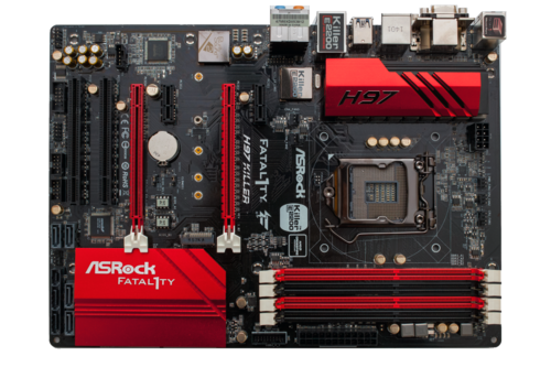
Example of an ATX motherboard (2010)


| No. | component | description |
|---|---|---|
| 1 | Processor socket |
Land Grid Array socket, here a socket 1366 for mounting an Intel Core-i processor . There is no processor in the socket and the protective cap is removed. |
| 2 | Chipset | Northbridge , an Intel X58 chipset (under the heat sink). |
| 3 | Chipset | Southbridge , an Intel ICH10 , connected to a heat sink of the northbridge by means of a heat pipe . |
| 4th | RAM slots | Slots for the main memory, in this case for DDR3 |
| 5 | PCI slots | For expansion cards. |
| 6th |
PCI Express - Slots |
three PCIe x16 slots (long) and one PCIe x1 slot (short). The blue slot (here on the right, upper in the usual installation arrangement) is reserved for the graphics card. |
| 7th | jumper | Small short-circuit plug for activating or deactivating settings (here: removing the voltage limit for overclocking). |
| 8th | Connections for front panel |
These are used to connect the mainboard and the front panel of the case: main switch, power indicator (On / Standby ), drive activity indicator. Furthermore, if available, the reset button and the built-in loudspeaker. |
| 9 | 24-pin ATX connector |
The main power supply for the motherboard through the power supply . With some older boards only 20-pin, but most power supplies are equipped with connectors that support both types of connection. |
| 10 |
8-pin ATX connector |
Connection for the power supply of the CPU. Often only 4-pin on older boards. Often also separable into two 4-pin ATX connectors. |
| 11 | External connections |
These connections protrude from the housing and serve as a connection for peripheral devices such as mouse, keyboard or USB devices and are adapted to the housing via the I / O shield . See below picture. |
| 12 | Internal USB ports |
About this z. B. USB ports on the front of the case or a built-in memory card reader connected to the mainboard. |
| 13 | AAFP sound connector | The sound inputs and outputs of the front panel are connected to this connector. |
| 14th |
Serial ATA - Connections |
Allows hard drives or optical drives to be connected to the motherboard |
| 15th | IDE connector | Also enables hard disks or optical drives to be connected to the mainboard. |
| 16 | Floppy disk connector | Allows the connection of the floppy disk drives. On the software side, only one drive is often supported. |
More pictures of typical motherboards

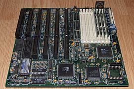
PC-XT compatible motherboard, manufactured with peripherals and logic blocks as already the IBM PC were used

AT motherboard for 80286 CPUs and 16-bit ISA slots, late 1980s

80286 Baby AT motherboard from 1988
Motherboard with 80386DX CPU in AT format, early 1990s

Mainboard from Dell System 325P with i386DX in LPX format, slots only via LPX riser card , built in 1990

AT main board for 80486 CPUs.

Socket 7 AT main board, with linear regulator for CPU voltages, built in 1996

Super Socket 7 ATX motherboard, with step-down converter for CPU core voltage, built in 1998 and 1999

Only four- layer ATX motherboard with Socket 462 for AMD CPUs and SiS735 chipset in one chip, built in 2001
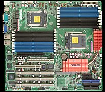
Server motherboard for two AMD Opteron CPUs

BTX format with Socket AM2

ATX motherboard for Socket 775 (supports Core 2 Duo / Quad), 2008, supports SLI . CPU and RAM are already installed.
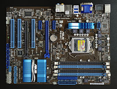
ATX - covered socket 1155 - the northbridge and usually a GPU are integrated into the CPU in this architecture, PCI and PCIe 1x and 16x, DDR3-RAM, 2011

Flex-ATX board with CPU and DDR3 RAM (northbridge and graphics are in the CPU)
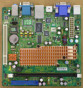
Mini-ITX board, CPU and chipset passively cooled 2008
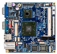
Nano-ITX board with removed heat sinks, S0 RAM socket, CPU soldered on 2008

Pico-ITX board with removed heat sinks, CPU soldered on 2008

.jpg)


