
PC power supply


A PC power supply unit , also called a computer power supply unit , is used to supply power to microcomputers . The mains alternating current is transformed into the lower direct voltages required in the computer , rectified, screened and regulated. It is designed as a switched-mode power supply . In the case of a PC, it is built into the housing of the computer; Laptops and some miniature PCs have external power supplies with similar characteristics. Built-in power supplies also contain fans which, in addition to self-cooling, are used in whole or in part to cool the components built into the computer housing.
properties

The basic properties of a PC power supply unit include the nominal power and the maximum load capacity of the voltage rails leading to the individual consumers in the computer with different DC voltages. As quality characteristics , a low apply noise , high efficiency , a fail-and-fluctuating power supply even with asymmetrical loads on the various voltage outputs. Additional equipment includes, for example, the continued running of the fan after it has been switched off to dissipate residual heat, removable cables , temperature-controlled fans or a specific design.
The voltage stability depends on the component quality and can only be determined by means of complex laboratory tests , the results of which are occasionally published in specialist journals and relate to the batch of the tested specimen. A test setup is defined by connecting a capacitor with 1 µF and 0.1 µF in parallel to the load and measuring with the oscilloscope at this point (for SFX power supplies with 10 µF and 0.1 µF and specified components). The oscilloscope is set to AC measurement, in which the DC voltage is decoupled .
Features such as short-circuit protection , a certain over-voltage (OVP) or overload protection (OCP) and 75 W power consumption of at least passive power factor correction ( English passive PFC ) are compulsory, but nevertheless sometimes advertised as special equipment. Gray imports can deviate from this, as these standards cannot be enforced worldwide.
rated capacity
The nominal power of a power supply unit describes the maximum power output guaranteed by the manufacturer. In current models, it is between 300 and 1000 W , but ranges from 120 W to 2000 W.
In addition to the total rated power, the technical data also indicates the load capacity of the individual voltage rails of the power supply unit. The value for 3.3 and 5 V is around 100 W regardless of the total power, the rest is distributed over the 12 V rail (s). In the case of high-quality power packs, the nominal power of the entire power pack is only given a rounded 12 V power, in the case of particularly simple models, on the other hand, the sum of all individual powers is partially rounded.
The nominal power required for a computer system depends on the components used, such as the motherboard , computer processor (CPU) , graphics processor (GPU) and hard drives . Power packs that are too tightly dimensioned cannot adequately compensate for power peaks, which can lead to stability problems that are difficult to isolate . Oversized power supplies are often only used to a fraction of their capacity, which reduces efficiency .
function


PC power supplies are switched mode power supplies based on the single-ended flux converter or the push-pull flux converter in parallel feed with a current doubler . AT and XT power supplies regulate the 5 V output voltage. This must be very stable in order to keep the PC working. The 12 V run through the same transformer . Therefore, the 12 V nominal voltage fluctuates in the defined load ratio of the 5 V and 12 V outputs within the specifications. The 12 V are used for drive motors, where the speed is always controlled.
The main transformers of typical 200 to 350 W power supplies have 19 to 28 turns of enamelled copper wire per 115 V, followed by a capacitively connected copper foil. 3 to 4 turns per 6 V are wound on the output side. Higher currents are achieved through parallel windings. The windings of the negatively polarized voltages partly have smaller cross-sections due to the lower output currents. Some output windings are designed as copper foil coils , whereby the capacitive copper foils are omitted. The following toroidal - storage inductors are wound with about 12 turns for the 5 V and about 26 turns for the 12 V.
Only with the ATX12V specification were CPUs and GPUs fed from the 12 V via step-down converters on mainboards and graphics cards. Since these converters generate output voltages below 3 V and are set depending on the respective CPU or GPU, they cannot be accommodated in the power supply unit. A more precise regulation of the 12 V was therefore not yet necessary. The storage chokes for 5 V and 12 V connected after the secondary rectifiers are wound over a common toroidal core . With some power supplies, the –5 and –12 V are wound in the same direction with enamelled copper wires with a smaller cross section. In the case of other power supply units, integrated voltage regulators ensure short-circuit protection. Transformers and secondary full-wave rectifiers use the midpoint connection for the positive output voltages. Clamping circuits are the exception in PC power supplies. Load resistors are used to keep outputs without a specified minimum load within the voltage specifications. For power supplies without control of the 3.3V output, a voltage-dependent load is connected downstream, such as the connected Zener diode TL431 / LM431.
Rarely and only with small output currents, the 3.3 V was generated from the 5 V via a series regulator and thus the voltage difference multiplied by the output current was converted into heat. In the most common method, the outputs of the main transformer for the 5 V are switched to the rectifier for the 3.3 V via one or two toroidal coils. This output voltage is generated by a phase shift in the pulse width modulation . For many power supplies, common information about the total output power of the 3.3 V and 5 V is specified. Since at low voltages and higher currents there is a considerable voltage drop in the line resistance of cables and plug contacts, the 3.3 V on the mainboard connector is scanned and fed back to the controller (+ 3.3 V feedback). In practice, the 3.3 V are fed and measured back with two lines in the same shoe of the ATX connector. Extensions and adapters between the power supply unit and the board can have a disruptive effect under high loads, as the extended cable section is not part of this control loop. In the mass segment, the universal switching voltage regulators "IR3M02", "TL494CN" and "KB7500B", which were not originally developed for PC power supplies, dominate in terms of pins and functions. They are housed in the secondary part so that they can measure the output voltage for regulation. Your control of the switching transistors also requires galvanic isolation . This takes place via further optocouplers or a signal transmitter (a smaller transformer). Since this signal transmitter has windings with an intermediate tap, this is the basis in many circuits to control single-ended flux converters and push-pull flux converters and to be able to transmit complementary pulses from the push-pull flux converter .
With the switching voltage regulator "KA3511" the three main output voltages of 3.3 V, 5 V and 12 V were regulated among each other. In order to compensate for changing loads on the rails, different chokes were used for a different phase shift in order to achieve the balance between 3.3 V and 5 V with the pulse width of the respective half-wave. With identical chokes, this ratio is regulated purely via the pulse width, with the 5 V being operated first and long pulses causing the 3.3 V to rise.
The early power supplies of the PC-XT had a small conventional transformer built in. This was not connected directly to the network, but rather like the choke of a passive PFC and works as such after switching on. With it, the controller was started when it was switched on before it could take care of itself. XTs with these power supplies have to remain switched off for some time after short power interruptions, since with charged filter capacitors on the primary side there is no sufficient voltage difference left to start the controller.
The small transformer was later replaced by a flyback converter -based switched-mode power supply, which made standby power supply possible. In the standby defined in the ATX standard , this auxiliary voltage is regulated to 5 V and routed to special circuits on the main board via the purple cable. This means that the PC is always connected to the power supply and can be switched on using the remote control like a television set . If the circuit around the controller of the main power supply is supplied or a fake error signal is switched off at the controller's error inputs, the PC switches on.
Most PC power supplies have an optocoupler that reports back when there is enough voltage at the output. Other power supplies regulate the +5 V SB in the secondary circuit, which can be cheaper to manufacture and does not have to apply to standby mode.
Power supplies for player PCs with an output power of over 600 W have additional, often separate 12 V rails for the CPU, graphics processors and drives. In newer ATX12V standards, changes of this type can be found from 350 W. It starts with a second double rectifier diode connected in parallel, a modified main transformer with additional windings for the 12 V rails and more powerful switching transistors. As a switched-mode power supply, they are technically interconnected like Siamese twins in order to limit component costs and to ensure short-circuit strength with identical cable cross-sections. Power supplies with two main transformers have also been manufactured. The various outputs for 12 V are marked with 12V1, 12V2, 12V3, 12V4, defined according to the EPS specification . In the upper performance segment, there are power supplies with a single 12 V rail that can deliver over 100 A on some models. This enables greater flexibility with the same performance, since when connecting the components you do not have to pay attention to the correct load distribution between the individual 12 V rails. This feature is advertised as a single 12 V power rail . The 3.3 V and 5 V are generated from the 12 V via separate step-down converters and regulate them independently.
As with laptops, external power supplies have also come into fashion for miniature designs of design, table, car and industrial PCs. In this way, the safety regulations for worldwide export can be more easily adapted to the target market by supplying a suitable power supply unit. Since this has only one output voltage, the other voltages must be generated in the computer. In 2005 the direct attachment of the converters in and on the connector of the main board was patented.
The PG signal (Power Good, with the AT the orange cable, with the ATX gray) is switched to 5 V via a timing element on a comparator . As soon as it carries 5 V, it is ensured that the power supply unit has built up its output voltages after switching on. For the mainboard this means that it can start operating. For this purpose, the internal reset signal, which is not sent directly to the reset button (Power On Reset, POR) , is no longer used. This part is processed by the clock generator .
Depending on the ATX standard version, 5 V SB (standby) are 100 mA, 1 A or 2 A available at 5 V when the PC is switched off (some ATX power supplies deliver 4 A and 6 A, deviating from the specification). This means that various switch-on logics are kept ready (some are optional for each main board):
- The circuit around the power button of the PC
- The network card, provided it supports switching on via the network ( WOL )
- An event (power event) on the PCI bus (from PCI version 2.2)
- Depending on the configuration, the keyboard, mouse and the keyboard controller are supplied via 5 V or 5 V SB for switching on at the push of a button.
- Dedicated USB ports for switching on e.g. B. via USB keyboard
- Pin 9 (= ring detect signal) of the serial interface for wake on modem
The power-on signal (not available with AT) carries 5 V SB via a pull-up resistor . If this green wire is switched to ground (0 V, the potential of the PC case), the power pack is activated. The current virtual switch position on / off of the PC is saved by the mainboard.
ATX connectors are available in two versions, ATX-20 and ATX-24. They are assigned identically in the 20 common pins. The newer four pins carry 3.3 V, 5 V, 12 V and 0 V (black) and are always connected through on the mainboard under the same voltage connections. The advantages of the additional pins are the associated lower contact resistance to the mainboard, as well as the contact security through redundancy of the 12 V.

Schematic diagram


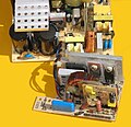
Structure of an XT power supply unit with a conventional transformer to supply the controller

XT power supply circuit board

XT power supplies had a power switch built into the power supply case

US Patent 7539023
Converter on the plug for use with a pure 12 V power source


.jpg)
Standby
With the introduction of the ATX standard, the auxiliary voltage generated in the power supply unit to supply the voltage regulator on the secondary side was tapped and fed to the main board as a regulated 5 volt standby voltage (+5 V SB). PCs can be switched on with this auxiliary voltage in response to external events and the on / off switch of the PC has become a button on the low voltage side.
Battery-operated devices connected to USB and supplied with power via +5 V SB can be charged when the PC is switched off, provided the device supports it. This includes cell phones whose chargers use the USB plug. Not every USB connection on the PC is connected to the + 5V SB voltage; it depends on the motherboard.
In addition, lights-out management systems such as the Intelligent Platform Management Interface (IPMI) are supplied via the +5 V SB and, in addition to remote monitoring of the running PC system, also enable switching on and off using appropriate remote maintenance programs.

Passive PFC
Active PFC


PFC
Sold in the EU electrical loads with nominal power above 75 W - and thus all PC power supplies - must have a power factor correction ( English Power Factor Compensation , therefore PFC abbreviated) feature. There are two types of construction: The passive version is comparatively cheap, heavy and has only limited effectiveness. The second, more expensive solution is an active filter, which also has a better effect. The 80-PLUS certification stipulates a power factor above 0.9, which is difficult to achieve with a passive PFC, so that in fact all 80-PLUS power supplies have an active filter. In practice, active PFCs range between 0.95 and 1. Input voltage adjustment, inrush current limitation and power factor correction are very closely linked in some designs and are also fulfilled by components designed on top of one another.
Input voltage switching
If this is provided, PC power supplies can be operated on power grids with different voltages. Switching can be done manually or automatically. Power supply units with a 115/230 V voltage switch are optimized for an average input voltage of 160 V and achieve their maximum efficiency . They have two capacitors connected in series with 200 V and at least 220 µF (at 250 to 300 W rated power). In order to distribute the voltage evenly across the capacitors, varistors (voltage-dependent resistors) are connected in parallel to the respective capacitor. In the 115 V position, the voltage switch bridges a phase of the mains voltage between the two capacitors. In this way, the bridge rectifier becomes a full- wave rectifier . This creates the classic voltage doubler in a Delon bridge circuit . When switching manually, which is usually done using a switch that can only be operated with a tool, there is a risk of immediate destruction of the power supply unit if the setting is incorrect.
Some power supply units have an automatic adjustment that allows operation between 100 V (sometimes from 80 V) and 240 V mains voltage. You can do this with an oversized 450V primary-side capacitor. The specifications of the passive PFC are thus largely met. If necessary, they are guaranteed by an inductance connected in series on the rectifier. This shifts the onset of current flow when the mains voltage exceeds the charging voltage of the capacitor. This choke used in the passive PFC causes unwanted induction voltages during operation on an uninterruptible power supply that does not output a sinusoidal voltage , which can lead to destruction. In some cases, 400 V capacitors are also used. These can represent a source of error, as the peak voltage plus mains voltage tolerance, interference voltages such as ripple and zero point shifts is temporarily above 400 V in practical operation at 230 V.
The empty input-side filter capacitors in PC and switched-mode power supplies cause high inrush currents , which put heavy loads on the switching contacts of the mechanical switches and can trigger fast-acting fuses. A fuse , mostly slow-acting, and an NTC (NTC thermistor) are connected in series in the input .
Simple active PFCs switch the rectifier to the capacitors via semiconductors, controlled by timing elements. Other active PFCs consist of an input-side switching voltage regulator , which takes on input voltage adjustment , inrush current limitation and power factor correction .
safety


PC power supplies are sealed. They are subject to various standards, such as the CE mark and the associated DIN-VDE standards part 8 contained in EN 60950, the European version of IEC 950, and EN 55022, in the device class of the use of the PC as a home or industrial device, whereby the office area offers and allows overlaps. The power supply unit supplies output currents of over 8 A and therefore needs to be operated in a suitable (PC) housing that prevents the melting cable from becoming a source of fire. With the ATX standard, all parts that carry mains voltage are housed back in the power supply unit. This was also the case with the IBM XT, whose switch in the power supply unit could be operated through a recess in the PC case. AT power supplies had a lead-out to the PC power switch, its connector or solder tags were sometimes insufficiently insulated, and in the car - technology 6,3er- used terminals , often backed up poorly against withdrawal. Often the prescribed protective conductor was mounted on a load-bearing screw and not dedicated. If the power pack has an IEC 60320 C13 socket (mains voltage output), both conductors are separated by the main switch (4-pin), otherwise a simple switch (2-pin) is sufficient.
There were power supplies on the market whose circuit boards did not meet the minimum distances between the primary and secondary circuits. There were also specimens that had an ungrounded common heat sink for components of the primary and secondary circuit. In addition, it should be noted that power supply units switch off when a malfunction is detected and the primary electrolytic capacitors can still carry dangerous voltage for up to 60 minutes after disconnection from the mains, provided the discharge resistors connected in parallel work, otherwise longer. Counterfeit, unsuitable and undersized electrolytic capacitors can burst and their aluminum foils and cup housings can connect live parts to the secondary side in a life-threatening manner and cause short circuits. The electrolytic capacitors are therefore glued to neighboring components in order to retain their components.
Efficiency

An important feature of a PC power supply unit is its efficiency , which depends on the technical quality of the construction and the electrical load. In general, a value of 80% is the lower limit for a power supply unit with “good” efficiency. The reason for this is probably the 80 PLUS campaign, for which a mean value is important, which is measured at the credit points at 20%, 50% and 100% load. The best power supplies achieve an efficiency of around 88% at 20% load and full load, and over 90% efficiency at 50% load. In the lower price ranges, models with an efficiency of less than 50% are still available. How the efficiencies look for other load values cannot be seen from the stated efficiency, but it is generally assumed that there are only small deviations; Individual power supply tests confirm this. The efficiency drops sharply at a load of less than 20%.
The latter leads to problems because the power supply market has become more and more disconnected from other developments in the PC market. Power supply units with an “80-PLUS” label are only available from retail outlets with a nominal output of 300 to 350 watts; Models with up to 90% efficiency often only from 500 watts. Technically, other things would be possible. For example, Dell is offering a 235-watt model that achieves an average efficiency of just over 90% at the test positions of 20%, 50% and 100%.
In contrast to this, a modern PC without a dedicated graphics card , as is often the case in the office sector, usually only consumes 40 to 50 watts when idling, which rarely rises above 100 watts under load. For this purpose, power supplies with a nominal output of a maximum of 200 to 250 watts would make sense in order not to fall below the 20% load. On the other hand, a power consumption of 350 watts is normally only exceeded when using high-performance graphics processors (especially so-called dual GPU cards such as Nvidia GeForce GTX295 or ATI Radeon HD 4870 X2 ). With even more extensive configurations, a power consumption of more than 1000 watts is possible.
Optimizing the efficiency depends on the filter capacitors used. The faster they age, the more often avoidable switching must be made, which entails a loss. The use of synchronous rectifiers on the secondary side would result in significant energy savings . Depending on the technology and semiconductor material, 0.7 to 0.3 V fall on diodes, while transistors can fall well below 0.2 V, which affects the 3.3 V and 5 V outputs in particular (with up to 10 W. Savings depending on the application), which no longer have to be emitted via the heat sink. Increasing the switching frequency range reduces and optimizes the transformers and also makes the switching transistors more expensive. Another loss can occur in the PFC due to the design .
lifespan

- Fan
The lubricants in the fan bearings are subject to an aging process , not least due to the absorption of abrasion . Fans are typically specified with 20,000 or 50,000 hours MTTF at an ambient temperature of 50 ° C, which corresponds to a continuous operation of 2.3 or 5.7 years. Higher operating temperatures shorten the service life considerably. Ball- bearing fans can always be operated in any position and tend to be more durable, but also louder than fans with plain bearings . The fan motors are electronically commutated DC motors that do not wear brushes.
- Electrolytic capacitors
Electrolytic capacitors dry out over time. Under their specified boundary conditions such as higher-frequency ripple and mixed currents and high temperatures (85, 105 or 120 ° C depending on the electrolyte), their service life is specified in hours - typically between 1000 and 6000 hours. The actual service life increases the further the distance is kept from this extreme load. An increase in the ambient temperature from 25 ° C to 45 ° C can reduce the service life by a factor of 10. This fact follows from the RGT rule . With these filter capacitors on the output side, in addition to their suitability for high ripple currents, the impedance is more relevant than the capacitance. Electrolytic capacitors of higher capacities usually have the lower impedance.
- Further influences on the service life
Common reasons for defective power supplies are failed MOSFETs . Furthermore, thermal paste that thermally couple the rectifiers and switching transistors to the heat sinks can harden or harden, which leads to inadequate cooling, just like heavy soiling of heat sinks or ventilation openings and insufficient air flow. Cable insulation and plug connections follow around 15 to 30 years after manufacture.
Connector systems
Since 2006, plug-in systems for internal connections have been offered for some power supplies - called "cable management" or "modular power supply" - and are registered as US patent 7133293 B2. There are several socket strips on the inside of the power supply unit. The cables to graphics cards and drives can be plugged into it, less often the connector for supplying the motherboard, which is always required and whose cables are led directly out of the power supply. On the one hand, these systems lead to greater flexibility, since cables that are not required can be removed in order to hinder the flow of cooling air less and to ensure a tidier interior of the PC case; the cables can also be offered in different lengths. However, these connections lead through the contact resistance at the connector to a slight deterioration in efficiency and higher susceptibility to loose connections can cause failure. Furthermore, the connectors of different power supply models are often not wired identically despite their apparently the same shape, so that the continued use of existing cables on another modular power supply can result in malfunctions or defects.
Passively cooled power supplies
A power supply unit that does not have a fan for heat dissipation but has relatively large finned coolers is referred to as “passively cooled” . A Peltier element is rarely used that allows larger amounts of heat to be dissipated, but because of its very poor efficiency it increases power consumption and produces heat itself, which further heats up the inside of the PC case and has to be dissipated in some other way. Passively cooled power supplies are themselves noiseless, the possibly required case and CPU fans or water cooling are not.
A modification are semi-passive power supplies that have a fan that is only switched on when required. This is the case with some power supplies, which on the one hand have a high degree of efficiency (~ 90%), which means that less waste heat is produced, and on the other hand cover a high performance range that may require additional cooling.
Redundant power supplies


Redundant power supplies are used in servers and important computers to increase reliability . Two or three power supply units are mounted in a common power supply cage. Depending on the design, the plug-in units can have a common or separate power supply line via the installation frame. This can be a weak point, as the electronics of the installation cage are only available once. Devices with a passive backplane , in which each slot has its own mains connection, are better . With separate inputs for the mains voltage, various fuses and optionally uninterruptible power supplies (UPS) can be switched. If one of the power supply units fails, the server continues to run without interruption. With separate inputs, the server continues to run if the UPS fails due to a defect, if only one input is looped through the UPS and the other module is still supplied with voltage. Only a double fault leads to failure. In 2002, compact, redundant power supplies, which correspond to the dimensions of standardized PC power supplies, were patented. Nevertheless, the housing requires an enlarged section and other positions for the screws.
Formats
The formats describe mechanical and electrical properties in order to make the respective power supply suitable for as many computers as possible.
The specifications include:
- External dimensions
- Mounting options such as the positions of the screws
- Airflow to cool the entire computer
- Connector dimensions
- Pin assignments
- Minimum number of plugs
- Cable lengths
- Output voltages
- Current per output voltage
- Efficiencies
Almost all IBM PC-compatible computers today are supplied with the same connector plug (SFX, TFX) according to the ATX format or a format related to it. The AT format was common until around the mid-1990s . There was also the short-lived BTX format in the era of the Intel Pentium 4 .
Dimensions and mounting options are specified in the housing standards, which only define the width and height, but not the depth. The use of a high-performance power supply unit can lead to a space problem that results in thermal problems, especially with small housings. The threads cut for the assembly of standardized power supplies are for 6-32 screws and correspond to the Unified Thread Standard .
There are manufacturers of complete PC systems and servers who deviate from the standards of the pin assignment. For reasons of cost, however, the same connector series are used. This is already obvious when you take a closer look at the cable colors and sequence.

AT format
| colour | Pin code | signal |
|---|---|---|
| orange | P8.1 | Power good |
| red | P8.2 | +5 V |
| yellow | P8.3 | +12 V |
| blue | P8.4 | −12 V |
| black | P8.5 | Dimensions |
| black | P8.6 | Dimensions |
| black | P9.1 | Dimensions |
| black | P9.2 | Dimensions |
| White | P9.3 | −5 V |
| red | P9.4 | +5 V |
| red | P9.5 | +5 V |
| red | P9.6 | +5 V |

| colour | Pin code | signal |
|---|---|---|
| yellow | 1 | +12 V |
| black | 2 | Dimensions |
| black | 3 | Dimensions |
| red | 4th | +5 V |
The AT power supplies ( Advanced Technology ) are based on a specification introduced by IBM in 1984. They differ from today's power supplies in particular in that they have a switch. These switches were originally located directly in the power supply unit housing and could be reached on the back or through a recess in the housing. Later, they were accommodated in the front of the PC case by means of a power cable extension, whereby there is no overarching standard for the type, mechanical design and assembly of the switch used.
You physically switch off the power supply and thus the PC on the mains voltage side, which means that standby functionality is not possible.
Furthermore, the power connection for an AT mainboard is designed with two mechanically identical but differently assigned connectors. Normally they are plugged next to each other, with the black marked wires facing each other. The two connector halves were not mechanically coded and could therefore be plugged in the wrong way round, which leads to a short circuit and mainly damage to the motherboard.

These power supplies offer plug connections:
- Two-part connector (2 × 6) for power supply of the main board (± 12 V, ± 5 V and GND)
- 4-pin Molex , product series 8981, or Tyco Electronics AMP 61314-1 for internal peripherals such as hard disks etc. Ä., 5 and 12 V, with 18- AWG cables . Used by IBM in computers since 1981.
- 4-pin BERG or AMP-171822-4 connector for floppy disk power supply (5 and 12 V) with 20 AWG cables
ATX format


ATX stands for Advanced Technology Extended . When they were introduced in 1995, these PC power supplies had the following connectors :

- Molex , product series 5566: 20 pin (pin assignment ) for the power supply of the main board, which replaced the two 6-pin power supply plugs of the AT main board
The following were adopted:
- Molex, product series 8981: 4 pin (for internal peripherals), which AsusTek used on motherboards since 2002, patented.
- The 4-pin BERG connector for powering floppy disk drives
Changed was adopted:
- optionally the 6-pin AUX connector, which was from the series of the AT motherboard connections
Also in newer versions:
- Molex, product series 5566: 24-pin instead of 20-pin (pin assignment ) for powering the motherboard (Molex 39-01-2240 24-pin)
- Molex, 5557 Series
- Molex: 15-pin plugs from the 67926 series with insulation displacement contacts or 67582 series with crimp contacts for S-ATA power connections for S-ATA devices
- Optional speed signal plug for connection to the main board to read out the power supply fan speed. Here only the speedometer signal is connected to pin 3. The fan is powered by the power supply unit itself. Therefore pins 1 and 2 are not used.
In more recent versions the following was omitted:
- the 6-pin AUX connector
- the cable for −5 V in the 20- or 24-pin motherboard connector
Intel has specified the connector according to manufacturer in the ATX standard and allows the use of compatible connector types. Other manufacturers have long been represented on the market. They are thanks to small modifications that make connectors more flexible.
The usual design of a PC power supply unit is a cuboid sheet metal housing , the same dimensions as the AT power supply unit, but rotated by 180 ° because the printed circuit board lay in the air flow. The power supply has a heating appliances socket according to IEC 60320 C14 for the mains voltage , optionally a power switch (in this case in rare cases - taken from the AT - a mitgeschaltete IEC socket according to IEC 60320 C13 for the power supply of the monitor ), and one or more fans . IEC-60320 C19 / C20 are used from 16 A input current at the latest, which occurs at 1472 W output and 115 V input at 80% efficiency . The fans are not only used to cool the power supply unit itself, but also to cool the computer as a whole, in that the air flow from the computer housing is conveyed to the outside through the power supply unit. Computer and power supply cases have various slots and openings through which the air flow passes.
In the case of powerful computers, the cooling effect of the power supply fan alone is usually no longer sufficient and must be supplemented by other measures, for example additional case fans.
The power supply unit is attached to the cutout in the back of the computer housing with four screws. There are special designs, e.g. B. water-cooled conversions. These are not defined in the ATX standard and rarely affect it. With water cooling on power supply units (or via power supply units in the event of a leaky system ), electrical safety must be observed. The safety regulations are designed in such a way that measures must be taken on the construction side to rule out a risk in the event of a fault.


PC power supplies must provide at least the following output voltages: +12 V, +5 V, +3.3 V, −12 V, +5 V SB (standby voltage), whereby according to ATX 2.0 to 2.2 at least two +12- V-rails must be available (this requirement was dropped again with ATX 2.3). The use of multiple 12 V lines is controversial, as these were originally intended to ensure a stable power supply with increasing load. According to the ATX specification (up to version 2.2), a 12 V line must not have more than 20 amperes before an additional line is required. It has been shown that the power supply manufacturers have no problems developing their power supplies so that they can provide a higher output well beyond 20 amperes. The short-circuit strength of extension, Y and adapter cables can be impaired.
The tensions are u. A. used for the following:
- +12 V: Voltage converter for CPU and graphics card, drive motors, fans
- +5 V: drives, USB ports, keyboard / mouse, older CPUs and graphics cards
- +3.3 V: traditionally for the chip and SIMM memory and for some of the motherboard parts, with older motherboards for the CPU
- −5 V, −12 V: are not used in all systems, e.g. B. sound cards, serial interfaces. The −5 V line is no longer compulsory in the new ATX standards and is therefore no longer available with every power supply unit.
- +5 V SB: only for standby mode

| width | height | depth | |
|---|---|---|---|
| ATX / BTX | 150 | 84 | 140 |
| ATX large | 150 | 84 | 180 |
| ATX - EPS | 150 | 84 | 230 |
| CFX | 101.6 + 48.4 | 86 | 96 |
| SFX | 125 | 63.5 | 100 |
| TFX | 85 | 65 | 175 |
| LFX | 62 | 72 | 210 |
| FlexATX | 81.5 | 40.5 | 150 |
The depth is a guideline for ATX and EPS. Powerful power supplies reach an installation depth of over 19 cm. The dimensions are important for installation in small housings.

| colour | signal | Pin code | Pin 1 | signal | colour |
|---|---|---|---|---|---|
| +3.3V | 1 | 13 (11) | +3.3 V + feedback 2 | ||
| +3.3V | 2 | 14 (12) | −12 V | ||
| Dimensions | 3 | 15 (13) | Dimensions | ||
| +5 V | 4th | 16 (14) | Power on | ||
| Dimensions | 5 | 17 (15) | Dimensions | ||
| +5 V | 6th | 18 (16) | Dimensions | ||
| Dimensions | 7th | 19 (17) | Dimensions | ||
| Power good | 8th | 20 (18) | −5 V 3 | ||
| + 5 V standby | 9 | 21 (19) | +5 V | ||
| +12 V | 10 | 22 (20) | +5 V | ||
| +12 V | 11 | 23 | +5 V | ||
| +3.3V | 12 | 24 | Dimensions | ||
|
|||||
- Voltage tolerances for ATX power supplies
All consumers ( hard drives , mainboard , optical drives , ...) should be connected when measuring.
| colour | signal | Tolerance ± | Min. | Max. |
|---|---|---|---|---|
| Dimensions | ||||
| +3.3V | 5% | +3.14 V | +3.47 V | |
| −12.0 V | 10% | −10.80 V | −13.20 V | |
| +5.0V | 5% | +4.75 V. | +5.25 V. | |
| −5.0 V | 10% | −4.50 V | −5.50 V | |
| +5.0V | 5% | +4.75 V. | +5.25 V. | |
| +12.0 V. | 5% | +11.40 V. | +12.60 V. | |
| Power on |


On the back of ATX power supplies there is usually a power switch that completely switches off the power supply to the power supply. The normal ATX switch on the case is not connected to the power supply, but to the motherboard. The effect is that the computer is not completely disconnected from the mains, but that power is consumed even when the computer is "switched off" (usually less than 5 W, if external USB devices are supplied, correspondingly more) via a " standby " circuit of the Power supply, and that the computer is enabled to be "woken up" via the power button (regular start), via a keyboard ("wake on key"), by a PCI or PCIe device, via a modem or network (" wake On Modem ”,“ Wake On LAN ”). With many firmware / BIOS versions there is the option of waking up the computer from the system time according to a schedule . The computer can also be woken up by many other events if it is supported by the firmware (e.g. by coreboot ). To do this, the main board puts the "Power supply on" signal (pin 16 for ATX-24, pin 14 for ATX-20) of the power supply plug to ground, after which the power supply goes into normal operating mode. These operating modes can be configured in the computer's BIOS . They only work when the power supply is connected and the power supply unit is in "standby" mode. Standby circuits have been criticized for their continuous power consumption. There are security risks if computers that can be woken up remotely are not secured, for example if they are equipped with a firewall that can be attacked in the start-up phase or should be designed for unsupervised operation after being switched on. Therefore these functions can be switched off on many motherboards.
BTX format
The thermally very demanding Pentium 4 processor required a special air flow regime inside the housing in order to be adequately cooled. For this purpose, the complex BTX (for Balanced Technology Extended ) format was developed, which includes various internal doors that have to remain closed during operation so that the cooling air flows to where it is needed.
The main difference between the power supply unit and the ATX is that it has a much higher performance than the usual ATX and an additional 4-pin 12 V plug, which is supposed to guarantee the interference-free transmission of the high currents of the 12 V circuits. This 12 V plug was also adopted into the ATX format as ATX12V - this means that ATX power supplies are electrically and mechanically completely identical to BTX power supplies and can be interchanged with one another. Motherboards and housings in the BTX standard could not keep up on the market and gave way to the ATX-compatible standards.
CFX format
This format, which was developed for smaller housings, can be seen as an extension of the BTX format. In the lower area, this power supply is only 101.6 mm wide and widens to 150 mm after 46 mm. The total height is 86 mm and the depth 96 mm.
| rail | colour |
|---|---|
| 12V1 | Yellow black) |
| 12V2 | yellow |
| 12V3 | Yellow blue) |
| 12V4 | Yellow-green) |
EPS format
As an extension to the ATX format, there is the EPS format (Entry Level Power Supply) for even more powerful power supplies for workstations and servers. Installation depths of 140, 180 and 230 mm occur here. Such power supplies found their way into desktops and are compatible with conventional ATX power supplies. However, instead of the 4-pin ATX12V connection, they have an 8-pin EPS12V connection (many power supplies also have both connections, usually on the same cable). Four 12 V rails are specified electrically, each delivering 20 amperes. The 12V4 rail is rated with up to 22 amps from 750 W total power supply unit output power. Overvoltage protection circuits are defined for EPS. The four-pin floppy connector has been changed to 22 AWG cable.
SFX format

To be able to manufacture even smaller computers, there is the SFX format. This was introduced by Intel in December 1997. The connection to the motherboard is made by the same 20- or 24-pin connector as with the ATX or microATX form factor. The output power starts at 160 W below that of an ATX power supply. The dimensions are (W × H × D) 125 mm × 63.5 mm × 100 mm, whereby the depth is not stipulated. Here you can find 40, 60 and 80 mm fans, some of which are also mounted outside the housing. Power supplies with a depth of more than 100 mm are also known as SFX-L power supplies. Typically 130mm deep to allow for 120mm fans.
TFX format

For flat housings (SFF = Small Form Factor) - mainly found in desktops - the TFX standard (Thin Format Factor) was developed by Intel in 2002. Connections correspond to the standard of the ATX power supply. The dimensions are (W × H × D) 85 mm × 65 mm × 175 mm; the total height with the fan grille is 70 mm. Deviating from the specification, there are power supplies in which the fan is mounted outside.
LFX format
The LFX (Low Profile Form Factor) format was developed by Intel in 2004. This format also uses the 24-pin ATX motherboard connector. This power supply is only 62 mm wide and 72 mm high, but 210 mm deep.
Non-standardized and proprietary formats
In addition to standardized formats, there are power supplies whose housing dimensions and properties differ from the current standards. Proprietary power supply formats can, for example, be due to a special housing cooling concept.
12 V concept
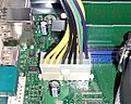
Connector on the motherboard of a Fujitsu 12 V power supply unit.

Type plate "12v concept power supply" 780W


In the 12 V concept, which is mainly used in office workstation computers with ATX and TFX formats, power packs are used that only provide a 12 V supply voltage. The power supply units only supply the mainboard with 12 V via a 16-pin connector. Longer cable harnesses with connections for drives or graphics cards are no longer available on the power supply unit. The drives are in turn supplied by a connection on the mainboard. Since the concept is used in office computers, as of 2017, less powerful power supplies with less than 300 W are usually available without the possibility of supplying powerful 3D graphics cards. An exception are power supplies for servers such as the Supermicro Twin Server, which provide higher performance via the 16-pin 12 V connection.
Advantages:
- The additional electronics in the power supply unit for 3.3 V and 5 V can be omitted. These voltages are generated by point-of-load voltage regulators (POL) directly on the mainboard. The power supply can thus be both cheaper to manufacture and more efficient at the same time. With this concept, these POL voltage regulators only have to be dimensioned somewhat larger.
- For the manufacturer, the cross-load problem becomes more manageable when composing the system. With conventional group-regulated ATX power supplies, it is possible that when there is a high power requirement, for example on the 12 V rail, the supply rail with 3.3 V or 5 V collapses and destabilizes the system. With the 12 V concept, only one voltage needs to be regulated on the power supply side.
- The cabling of the computer can be clearer. This makes the system easier to ventilate. The problem of having to safely stow an ATX cable harness that is too long in the housing is eliminated.
- In addition, with the power supply of the drives through the mainboard, efforts are anticipated to lead the power and data lines of the drives in a common connection in the future. As a result, it would also be conceivable to operate solid-state drives in particular with lower voltages. Due to the compatibility with old power supply units, which can only supply the drives with 5 V and 12 V via Molex adapters, 3.3 V has not become established for the supply of SATA drives. The supply of drives with 3.3 V has been removed from the SATA standard from version 3.2.
The 12 V concept is not yet an industry standard , but it is spreading more and more and is being implemented individually by system manufacturers such as Fujitsu, HP or Dell, especially for small desktop systems and servers.
Other use
In principle, PC power supplies can also be used to supply power to other circuits, provided that the specifications of the circuit and power supply are in harmony and they are installed in accordance with the safety guidelines. The supply of unfiltered high-frequency loads is not defined. Operation outside of suitable enclosures already violates Directive 2006/95 / EC (Low Voltage Directive) . Manufacturers secure themselves with clauses in the guarantee, safety instructions and conditions with formulations such as "For the intended use only".

Web links
- Specifications of each form factors (English)
- Certification company energy efficient power supplies (English)
- Everything about the various cables and connectors of the PC power supply (English) from July 15, 2008
Individual evidence
- ↑ a b c d e f g h i j k l Gabriel Torres: Everything You Need to Know-about Power Supplies , hardwaresecrets.com of May 29, 2008
- ↑ a b intel (formfactors.org): SFX12V Power Supply Design Guide, Version 2.3 ( Memento from April 14, 2016 in the Internet Archive ) (PDF; 366 kB) from April 2003
- ↑ a b c d intel (formfactors.org): TFX12V (Thin Form Factor with 12-Volt Connector) Power Supply Design Guide Version 2.1 ( Memento from March 8, 2016 in the Internet Archive ) (PDF; 421 kB) from July 2005
- ↑ Gabriel Torres: Why 99% of Power Supply Reviews Are Wrong , hardwaresecrets.com of May 29, 2008
- ↑ Nathan Kirsch: Sneak Peak - Ultra Products 2000W ATX Power Supply from January 3, 2007
- ↑ a b c d e f g h i j Gabriel Torres: Anatomy of Switching Power Supplies , hardwaresecrets.com of October 26, 2006
- ↑ Dismantling FSP250 / FSP300 / FSP350, BJ1998; Suntec 230APSA, BJ1996
- ↑ LM431 , on ti.com
- ↑ Datasheet KA3511 , Fairchild Semiconductor Corporation, 2001
- ↑ Inside view of a 1475W power supply
- ↑ Silent Pro Hybrid 1300W , on coolermaster.com
- ↑ Silent Pro Hybrid 1300W data sheet , accessed on October 12, 2013
- ↑ US patent 7539023 : Monolithic plug-in power supply (PDF; 733 kB), registered December 15, 2005, published May 26, 2009
- ↑ Data: Thermaltake Mod. Toughpower XT Gold 1475W
- ↑ Data: Silverstone Mod. SST-ST1500
- ↑ Daniel Schuhmann: Benchmarks ATX12V 2.0 Efficiency Under Load 20% and 100% on tomshardware.com from February 28, 2005
- ↑ Igor Wallossek: Power supply practice: How much power supply do people really need? And above all: which one? on tom's hardware from March 10, 2011
- ↑ 80 PLUS Certified Power Supplies and Manufacturers of October 10, 2013, accessed October 13, 2013
- ↑ see c't 07/09, p. 151, “test stand | x86 CPUs "
- ↑ Power consumption (note: the processor in the test is so overclocked that its idle power consumption significantly exceeds any processor that can be bought at the time.)
- ↑ legitreviews.com: "Intel recommends a kilowatt or better PSU for a system with 4 GB of memory, two GPUs, and two CPUs. If you want to run four GPUs and 8GB of memory, they recommend a PSU rated for over 1400 W! "
- ↑ OklahomaWolf: Reviews - X-650 650W , October 11, 2009, accessed October 12, 2013
- ↑ Gabriel Torres: ST60F PS Power Supply Review , March 21, 2013, accessed October 12, 2013
- ↑ Gabi Schlag and Dörte Wustrack: Repair instead of throwing away - Against the planned product death in SWR2 “Knowledge” from December 16, 2013
- ↑ Achim Sawall: Planned Obsolescence - Federal Environment Agency is looking for predetermined breaking points in electronics in Golem.de online from August 19, 2013
- ↑ Reliability Considerations for Power Supplies , on de.cui.com
- ↑ IBM: Why do Power Supplies Fail, and What can be done about it? (English, 2005, accessed October 2015)
- ↑ U.S. Patent 7133293: Personal computer power supply installed within a case of a personal computer , registered September 8, 2004, published November 7, 2006
- ↑ US Patent 6700778 B1 (= CN2572462Y): Fault-Tolerant Power Supply Module for Personal Computer Processor, filed on Sept. 28, 2002, registered on Apr. 7, 2003, published on March 2, 2004
- ↑ a b US patent 6827589 B2 : Motherboard with a 4-pin ATX power male connector , registered on March 14, 2002, published on December 7, 2004
- ↑ a b c EPS12V Power Supply Design Guide - A Server System Infrastructure (SSI) Specification for Entry Chassis Power Supplies (PDF; 412 kB) Version 2.91
- ↑ c't hotline: Mainboard without ATX power connection. Retrieved March 10, 2017 .
- ↑ Fujitsu: Whitepaper 12V only power concept. Retrieved March 10, 2017 .