
Capacitor Plague


The early massive failure of aluminum electrolytic capacitors with liquid electrolytes, which began at the end of 1999, mainly concerned electrolytic capacitors from Taiwanese manufacturers and in the years 2002 to 2007, was referred to as Capacitor Plague ( German : capacitor plague) or "Badcaps" (German: bad capacitors) led to high failure rates for PC motherboards , power supplies , LCD monitors and many other electronic devices. The failures were caused by water-driven corrosion and could be traced back to a defective electrolyte. According to statistical calculations, the problematic Taiwanese capacitors manufactured with them had failed by the end of 2007.
Aluminum electrolytic capacitors with liquid electrolytes, which appear noticeable in devices after the end of 2007 and later with manifestations similar to the "Capacitor Plague" and have led to device malfunctions, however, will most likely have reached their natural end of life due to drying out. Appearances of this kind are not unusual in electrolytic capacitors that work with a very high proportion of water in the electrolyte.
Possible reason: industrial espionage
The massive failures of aluminum electrolytic capacitors with liquid electrolytes , or "electrolytic capacitors" for short, in the years 1999 to 2007 are due to millions of faulty capacitors from Taiwanese productions by several manufacturers, mainly in PCs, on mainboards , PC power supplies , in LCD - Monitors and power supplies were used and failed prematurely after a few months of operation. Many of the electrolytic capacitors used were the life specified (load life) of 2000 h / 105 ° C. With an average internal temperature of a PC of 45 ° C and a ripple current that corresponds to the data sheet specification, these capacitors have an expected service life of around 15 years of continuous operation. In the event of a failure after 1.5 to 2 years, one can really speak of "prematurely".
The failure patterns were quite spectacular: burst electrolytic capacitors, pressed out rubber stoppers and leaked electrolyte were found on countless circuit boards. Many well-known device manufacturers such as Dell , Cisco , Intel , Asus and Abit had to carry out product recalls or assume repair costs because of these capacitors. Many repair instructions for self-help can also be found on the Internet.
Industrial espionage in connection with the theft of an electrolyte formula is regarded as the likely cause of the faulty electrolytic capacitor production. When moving from Japan to Taiwan, an electrolyte developer probably took the chemical composition for a new low-resistance, inexpensive, water-containing electrolyte with him and then tried to recreate this electrolyte in Taiwan in order to be able to sell it more cheaply than the Japanese. However, the formula was apparently only partially copied; important substances to ensure the long-term stability of the capacitors were missing.
Development of electrolytic capacitors with water-based electrolyte systems
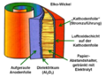
- Structure of an aluminum electrolytic capacitor with liquid electrolyte
Representation of an electrolytic capacitor with the layer sequence of the foils
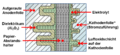
Cap principle and section through the layer sequence of the cap construction


The very first electrolytic capacitor was an aluminum electrolytic capacitor with a liquid electrolyte, invented by Charles Pollak in January 1896. In principle, the "electrolytic capacitors" have remained the same to this day. The very thin dielectric made of aluminum oxide, grown by forming, is located on an aluminum anode. The liquid electrolyte adapts to the structure of the dielectric, forms the cathode of the capacitor and thus makes the thin layer of the dielectric effective. A spacer made of paper prevents direct contact between the oxide layer and a second aluminum foil (cathode foil), the power supply, to the liquid electrolyte and also stores it. Sealed and provided with connections, this structure results in the inexpensive and generally quite reliable "electrolytic capacitors" used billions of times in electronic devices.
The electrolyte as ion conductor causes a large part of the ohmic losses in the electrolytic capacitor. Great efforts have been made over the years to reduce these losses so that the "current carrying capacity" ( ripple current ) can be increased, because without such improvements, dimensions cannot be reduced .
In Japan, as part of these developments, new, low-resistance water- based electrolytes were developed in the mid-1980s , the conductivity of which was significantly improved compared to electrolytes with organic solvents . With its very high permittivity of ε = 81, water is an effective solvent for electrolytes. As such, it dissolves salts , which give the electrolyte its conductivity, in high concentration. The high concentration of the ions dissociated in the electrolyte results in better conductivity. But water reacts violently with unprotected aluminum . It converts aluminum (Al) into its hydroxide (Al (OH) 3 ) in a strongly exothermic reaction . This is accompanied by strong heat and gas development in the electrolytic capacitor and can lead to the capacitor bursting. Therefore, the main problem in the development of the new water-containing electrolyte was to get a grip on the aggressiveness of the water towards aluminum, so that the capacitors also have a sufficiently good long-term stability.
In the late 1990s, the Japanese manufacturer Rubycon was a leader in the development of new water-containing electrolyte systems with improved conductivity. In 1998 Rubycon launched the "Z-Series" with the two series ZL and ZA, the first capacitors that worked with an electrolyte with a water content of around 40% and were suitable for a wide temperature range from −40 to +105 ° C .
The improvement in the conductivity of the electrolyte results from a comparison of two capacitors, both of which have a capacitance value of 1000 µF at a nominal voltage of 16 V and size DxL = 10x20 mm. The capacitors of the Rubycon series YXG, which are provided with an electrolyte based on an organic solvent, can be loaded with a ripple current of 1400 mA at an impedance of 46 mΩ. On the other hand, capacitors of the ZL series with the new water-containing electrolyte can be loaded with the ripple current of 1820 mA at an impedance of 23 mΩ, an increase of 30%.
Other manufacturers such as Nippon Chemi-Con , Nichicon , Elna etc. followed a short time later. The new series were touted as “Low ESR” or “Low-Impedance”, “Ultra-Low-Impedance” or “High-Ripple-Current-Elkos”. The highly competitive market in digital data technology and power supplies quickly took up this new development, because by improving the conductivity of the electrolyte, the electrolytic capacitors were not only able to cope with a higher ripple current load, they were also cheaper because water is quite cheap. Better and also cheaper, for mass products such as PCs, DVD players and power supplies, the cost argument was the decisive factor.
Aluminum oxide - stable dielectric and protection against corrosion

From an electrical point of view, the electrolyte in an electrolytic capacitor is the actual cathode of the capacitor. On the other hand, it is also a chemical, an acid or a lye , which must be chemically inert so that the capacitor, whose components are made of aluminum , remains stable over the long term. But aluminum is a very base metal that easily binds with oxygen . And water-based acids are quite aggressive towards aluminum. Only a stable aluminum oxide layer Al 2 O 3 on the surface of the metal and so-called inhibitors or passivators in the electrolyte protect aluminum from aggressive reactions with the water and prevent water-driven corrosion. The problem with water-containing electrolyte systems therefore lies in controlling the aggressiveness of the water towards aluminum.
This problem has dragged on through the development of electrolytic capacitors for many decades. Because even the first technically used electrolytes in the middle of the 20th century were mixtures of ethylene glycol and boric acid . But even with these so-called glycol electrolytes an unwanted chemical water of crystallization reaction occurred, according to the scheme: “Acid + alcohol” becomes “ester + water”.
In an initially anhydrous electrolyte, an esterification water with a water content of up to 20% is created. These electrolytes were originally only suitable for a limited temperature range from −25 to +85 ° C. They had a voltage-dependent service life, because the aggressiveness of the water, especially at higher temperatures due to corrosive effects, caused the residual current to rise exponentially with increasing voltage, and the associated increased electrolyte consumption resulted in faster drying. Even newer glycol electrolytic capacitors, which no longer have any corrosive effects, still have a low dependency of the service life on the applied voltage.
On the other hand, water also provides the oxygen during the self-healing of the electrolytic capacitor, when reforming the anode oxide, the dielectric of the capacitor. This is because, depending on the pH and temperature , ions from the electrolyte can diffuse into the oxide of the dielectric during storage times and change the crystal structure. On the one hand, this can result in electrical defects in the oxide and, on the other hand, this can weaken the dielectric, which leads to a reduction in the insulation resistance. Both effects lead to an increased residual current when a voltage is applied , which, however, decreases again due to the formation of aluminum oxide. This normal process of reforming takes place in two reaction steps. First it converts aluminum (Al) into its hydroxide Al (OH) 3 in a strongly exothermic reaction :
- 2 Al + 6 H 2 O → 2 Al (OH) 3 + 3 H 2 ↑
This reaction is accelerated by a high electric field and high temperatures and is accompanied by a pressure build-up in the condenser due to the released hydrogen gas .
The gel-like aluminum orthohydroxide Al (OH) 3 , also known as aluminum hydroxide , aluminum hydrate or aluminum trihydrate (ATH), converts into the crystalline form of aluminum oxide Al 2 O 3 in the second reaction step, usually slowly in a few days at room temperature and more rapidly at higher temperatures :
- 2 Al (OH) 3 → 2 AlO (OH) + 2 H 2 O → Al 2 O 3 + 3 H 2 O
The stable dielectric of the capacitor is only formed by the stable aluminum oxide newly created during the reforming process, with which the flaws on the anode of the electrolytic capacitor are healed. It also protects the capacitor from the aggressive reactions of aluminum in the presence of water. However, a small amount of water is removed from the electrolyte during the conversion process. Electrolyte is "used up".
Aluminum hydroxide - loss of self-healing


The aluminum oxide layer in the electrolytic capacitor is resistant to chemical attack as long as the pH value of the electrolyte is in the range from pH 4.5 to 8.5. However, the pH value of the electrolyte should ideally be slightly acidic (pH = 5) to about 7 (neutral). Measurements of the residual current, which were already carried out in the 1970s, have shown that the residual current increased, i.e. chemically caused defects appeared as soon as the pH value left this ideal range.
It is also known that the “normal” course of the formation of aluminum oxide from aluminum via the intermediate step from aluminum hydroxide to stable aluminum oxide can be interrupted by a basic electrolyte. The following reaction serves as an example of the chemistry of this interruption:
- 2Al (s) + 2NaOH (aq) + 6H 2 O → 2Na + (aq) + 2 [Al (OH) 4 ] - + 3H 2 (g)
In this case it can happen that the hydroxide formed in the first step becomes detached from the aluminum surface, does not transform into the (desired) aluminum oxide and the cause of the oxide formation, a defect or the weakening in the dielectric, is retained and the Defect is not healed. Then there is another new formation of aluminum hydroxide at this point without conversion into the stable aluminum oxide. Self-healing in the electrolytic capacitor (reforming) no longer takes place. The reactions do not come to a standstill, the pores in the anode foil grow closed with the hydroxide and the hydrogen gas produced during the reaction creates an ever increasing pressure in the electrolytic capacitor.

Proof of wrong electrolyte
- Pictures of an open failure capacitor

Removed electrolytic capacitor with partially unwound foils
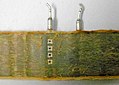
Unwound electrolytic capacitor roll, the foils stick together firmly


This situation of unchecked hydroxide formation (English: hydration ) and the associated gas formation was what led to the incident known as “ capacitor plague ” or “ bad caps ” with the massive failure of aluminum electrolytic capacitors. It was proven by the investigation of failed capacitors from Taiwanese manufacturers by C. Hillman and N. Helmond.
These two University of Maryland scientists first used ion exchange chromatography and mass spectrometry to determine that it is actually hydrogen gas that causes the electrolytic cap cups to bulge and the cup valve to open. This proved that the oxidation takes place according to the first stage of the formation of aluminum oxide.
Because it is customary in electrolytic capacitors to bind the hydrogen formed with the help of reducing compounds in order to reduce the resulting pressure, compounds of this type were then searched for. Mostly aromatic nitro compounds or amines are used for this. Although the research methods used above are very sensitive, no pressure-reducing compounds could be found. In the case of capacitors whose internal pressure build-up was just so great that the cup was already bulged, but the valve had not yet opened, the analysis of the electrolyte showed that the electrolyte in the defective capacitors had an alkaline, basic pH value (7 <pH <8). Comparable Japanese electrolytic capacitors, on the other hand, had an electrolyte with a pH value in the acidic range (pH ≈ 4). Since it is known that aluminum can be dissolved in alkaline liquids, but not in acidic media, the electrolyte from the defective capacitors was then examined using an EDX fingerprint analysis and it was actually possible to determine dissolved aluminum.
To protect the aluminum against the aggressiveness of the water, phosphate compounds, so-called inhibitors or passivators, are used when it comes to long-term stable, water-containing electrolytic capacitors. Since the examined Taiwanese electrolytes lacked phosphate ions and the electrolyte was also alkaline, they lacked protection against the water and the further formation of stable aluminum oxide was stopped. Only aluminum hydroxide was produced unchecked.
The chemical result of the investigation was underlined by the electrical measurement of the capacity and the residual current in a long-term test over 56 days. The chemical attack on the oxide layer of the capacitors weakened it, so that after a short time the capacitance and also the residual current increased before both parameters dropped rapidly after the valve was opened.
The Hilmann and Helmond report provided proof that the cause of the failure was actually a faulty electrolyte used by the Taiwanese manufacturers; the ingredients required for the long-term stability of the electrolytic capacitors that were supposed to ensure the stability of the capacitors were missing.
The fact that the electrolyte, with its pH value lying in the basic range, then resulted in the fatal unchecked hydroxide formation can be proven both photographically and with an EDX fingerprint analysis of the chemical components of the surface oxide.
Even a microscopic image with a 10x magnification, as shown in the pictures on the right, shows a clear change in the structure of the anode surface. On the surface of the "fresh" anode from an unused electrolytic capacitor, the grooves from the direction of travel of the anode, which arise in the manufacturing process, are clearly visible. However, the magnification was not sufficient to show the openings of the pores in the anode. On the anode, which comes from a failed electrolytic capacitor from Taiwanese production, the surface is overgrown with a plaque-like substance across the direction of travel. An EDX fingerprint analysis then showed the chemical difference in the surface oxide. The surface of the "fresh" electrolytic capacitor was covered with the stable aluminum oxide. The surface of the failed electrolytic capacitor was, as evidenced by the significantly higher oxygen peak, covered with aluminum hydroxide.
Electrical effects


A somewhat different electrical behavior in almost all electrolytic capacitors with water-containing electrolytes can be measured compared to electrolytic capacitors with electrolyte systems based on organic solvents. The inrush residual current after storage times is at a higher level. If, however, a water-containing electrolyte is still in a stable state, ie has not yet reached the basic pH range, the residual current will set itself to a low value after a few minutes. The defects that had formed on aluminum due to the aggressive behavior of the water are quickly healed. If, however, the electrolyte has lost its stability during operation and has drifted into the basic range, the self-healing process ends after the formation of aluminum hydroxide. The subsequent conversion into the stable aluminum oxide is prevented by the basic environment. The flaws that cause the residual current remain unprotected, only covered by hydroxide, and can be further attacked by the water.
The dielectric strength of this hydroxide will only reach the level of the applied operating voltage, which is usually significantly lower than the nominal voltage. This reduced dielectric strength of the anode can also be measured. Such a measurement result is shown in the picture on the right. The reduced dielectric strength compared to the original anode dielectric strength shows that a chemical process has permanently damaged the oxide layer of the dielectric.
As a result of this damage, the thickness of the insulating layer, the effective dielectric, becomes smaller. According to the formula of the plate capacitor, this means

in which ε is the permittivity, A is the electrode surface and d is the distance between the electrodes, which increases with a thinner dielectric, the capacitance value. In fact, an increase in capacitance to a higher value can be measured with electrolytic capacitors in which the unchecked hydroxide formation has already begun but the electrolytic capacitor has not yet burst, as the measurement curve of the capacitance profile shows in a service life test in the picture above right.
The end stage of one of these processes is reached when the pressure in the condenser has risen so high due to the constant and ever faster unchecked formation of hydroxide that the valve opens or the rubber stopper is pushed out. Put simply, it bursts. If the capacitor is then open, it dries out very quickly, loses its capacity down to a minimum value and the ESR increases significantly up to the kΩ range. Since the ripple current continues to flow through the remaining capacitor, the capacitor winding will heat up considerably at higher currents and the paper of the winding will turn a clear brown color.
Reasons for electrolytic capacitor failures after 2007


The first press publications about the massive occurrence of failures appeared in September 2002. It can be assumed that by mid-2003 at the latest, the manufacturers concerned changed their production and resorted to a "correctly" composed electrolyte. With a reduced service life of around 1.5 to 3 years, the last of the faulty capacitors should actually have failed by mid-2006. On the internet, 2007 is often cited as the end point for failures with defective electrolytes. After this date, no further incidents should occur. But even after 2007, the year in which the failures of the Taiwanese capacitors with the wrong electrolyte should actually be over, the reports with failed capacitors can be found on the Internet. The problem of the bursting electrolytic capacitors still exists, because the failure patterns described with bursting electrolytic capacitors and squeezed out rubber stoppers are identical to the failures of that time.
These failures affect electrolytic capacitors for nominal voltages from 6.3 V to 100 V, which have one thing in common: they have a water-containing electrolyte with a very high water content of up to 75%. In the manufacturers' catalogs they are identified under "Low-ESR" -Elkos or also with "Low-Impedance", "Ultra-Low-Impedance" or "High-Ripple-Current-Elkos". These electrolytic capacitors must not be confused with aluminum-polymer electrolytic capacitors, which are also often called "low ESR electrolytic capacitors". Only aluminum electrolytic capacitors with liquid electrolytes are affected .
If failures of the type described above occur on electrolytic capacitors with a more recent date of manufacture, it cannot be due to the incomplete electrolyte from the earlier Taiwanese production. If aluminum hydroxide is detected in an SEM and EDX analysis of the failed electrolytic capacitor, the electrolyte is not automatically defective because the circuit layout may also have been incorrect. Therefore, two questions must first be answered:
- Was the ripple current and temperature load on the capacitors correct?
- Did the failures occur prematurely or at the end or after the service life had expired?
It should be noted that the commonly used 10-degree rule ( Arrhenius rule , RGT rule ) for estimating the capacitor service life (the service life doubles for every 10 ° C reduction in temperature) often does not apply to the capacitors with water-containing electrolytes . The 10-degree rule only applies if it has been confirmed by the respective capacitor manufacturer. Because some manufacturers specify other service life calculation formulas, sometimes even different formulas for their different series. Even if a graphical method for estimating the capacitor life is specified by a manufacturer and these curves seem to follow the 10-degree law, you should not be fooled. The slope according to the 10-degree rule in this example is different from the specified curve shape.
The two following examples of an electrolytic capacitor life calculation are intended to show the difference in the results between the 10-degree formula and the formula specified by the manufacturer Rubycon for the ZL series with water-based electrolytes.
For a PC power supply, an electrolytic capacitor with a service life specification of 1000 h / 105 ° C is selected. The average operating temperature of the capacitor, measured in the metallic area of the predetermined breaking point, is 45 ° C. In the first example, the ripple current load corresponds to the data sheet value (100%), in the second example it corresponds to twice the data sheet value.
- 10 degree rule: 64,000 h, 7.3 years
- Rubycon formula: 64,000 h, 7.3 years
A ripple current load with twice the data sheet value results:
- 10 degree rule: 22,600 h, 2.6 years
- Rubycon formula: 6000 h, 0.7 years
The calculated service life at twice the value of the ripple current is significantly shorter according to the Rubycon formula than according to the 10-degree formula. This expresses the fact that the operation of electrolytic capacitors with water-containing electrolytes can be problematic when overloaded. This is also expressed in a warning note from many electrolytic capacitor manufacturers, in which operation with a ripple current higher than the specified value is warned:
- Do not apply a ripple current exceeding the rated maximum ripple current.
The difference in the shortening of the service life with a higher load of electrolytic capacitors with water-containing electrolytes compared to those with electrolytes based on organic solvents is to be found on the one hand in the aggressiveness of the water towards the aluminum. Electrolytic capacitors with solvent electrolytes such as GBL have a significantly better residual current behavior, which means that less electrolyte is consumed during operation and can therefore even have an effect up to the specification for estimating the service life of a capacitor. On the other hand, water-containing electrolytic capacitors consume more electrolyte than solvent electrolytic capacitors due to the higher residual current, which reduces the service life of the capacitors.

On the other hand, a high ripple current load can also result in the consumption of electrolyte, because a physical effect occurs especially when the capacitor is discharged, which under certain circumstances can lead to the cathode foil in the capacitor being formed. The cathode foil is only covered with an oxide layer that is naturally formed on the aluminum surface through contact with the air. This oxide layer has a dielectric strength of about 1 to 1.5 V at room temperature; at 105 ° C. this dielectric strength drops to about 0.7 to 1.2 V. If a charged capacitor is discharged, the polarity in the capacitor is reversed: the cathode becomes an anode and the current flows out of the capacitor. A voltage of opposite polarity then builds up on the cathode foil via the voltage distribution at the contact and line resistances, which in the case of a ripple current load up to the specified data sheet value does not result in any reforming of the cathode foil with the formation of a thicker oxide layer if the cathode capacitance C K very large relative to the anode capacitance C A is. This is usually the case when the cathode capacity is greater than the anode capacity by a factor of 10. At higher ripple current values, especially when the operating temperature is also high, forming processes can occur. The formation of the new, more stress-resistant oxide layer is associated with a loss of electrolyte.


The service life of electrolytic capacitors with a high water content in the electrolyte is not only determined by the operating temperature and the associated gradual evaporation of the electrolyte, but also by the residual current behavior and a possible formation of the cathode foil in the event of high ripple current loads. All influencing variables, the ambient temperature, the higher residual current over the operating time and the formation of the cathode foil in the event of ripple current overload "consume" electrolyte fluid. From a certain point on, the salts dissolved in the electrolyte will crystallize out to the saturation limit. The electrolyte changes, initially the conductivity of the electrolyte decreases, the ESR increases. The change in the electrolyte also has an impact on the pH value in some product series; the pH value can change, the more so the closer it comes to the end of the life of the electrolytic capacitor. If the pH value in the electrolyte goes into the basic range at the end of its service life, which is often found in electrolytic capacitors with water-containing electrolytes, then, as described above, the regeneration of the imperfections stops and the fatal, unchecked aluminum hydroxide formation begins. If this behavior now coincides with the calculated end of life of the electrolytic capacitors and the capacitor bursts at the end of the life, it looks as if a new case of the "capacitor plague" has occurred.
The failure patterns, burst electrolytic capacitor, rubber stopper pushed up, leaked electrolyte are identical to those from production with the "wrong" electrolyte. So, if failures of this type still occur after 2007, it can only be determined by a careful recalculation of the entire circuit with all boundary conditions for the capacitor such as temperature and ripple current load, whether it is a fault in the capacitor or a fault in the design of the circuit. Because only if the capacitor has failed prematurely, i.e. before the end of its service life, can a defective electrolyte be assumed. Perhaps the legal dispute between a well-known computer hardware manufacturer and an electrolytic capacitor manufacturer, as can be seen from a publication in the "Techreport", can be traced back to an incorrectly performed calculation of the electrolytic capacitor load and the electrolytic capacitor life.
However, bursting an electrolytic capacitor is an extraordinary process, even if it has reached the end of its service life. So far, it could be assumed that electrolytic capacitors did dry out over time, but did not show any external irregularities even when they were dried out. It seems that some manufacturers' water-based electrolytic capacitors burst at the end of their service life. Once the electrolytic capacitor has burst, it is no longer possible to determine whether thermal or electrical overload caused the valve to open or whether the failure occurred prematurely due to poor coordination of the electrolyte with subsequent hydroxide formation. In order to correctly assess recent electrolytic capacitor failures, it is absolutely necessary to determine the exact operating conditions of the application and to carry out a service life estimate in accordance with the manufacturer's specification.
Coding of the date of manufacture
Many Elko manufacturers use a two-digit code to encrypt the date of manufacture (Date Code)
- First digit: year of manufacture, S = 2004, T = 2005, U = 2006, V = 2007, W = 2008, X = 2009, A = 2010, B = 2011, C = 2012, D = 2013, E = 2014, F = 2015
- Second digit: month of manufacture, 1 to 9 = Jan. to Sept., O = Oct., N = Nov., D = Dec.
- Example: X8 = August 2009
Individual evidence
- ↑ Badcaps.Net, Forum
- ↑ Capacitor plague, identified manufacturer
- ↑ Low-ESR Aluminum Electrolytic Failures Linked to Taiwanese Raw Material Problems ( Memento of the original from April 26, 2012 in the Internet Archive ) Info: The archive link was inserted automatically and has not yet been checked. Please check the original and archive link according to the instructions and then remove this notice. (PDF; 417 kB)
- ↑ Heise online, April 14, 2005, the mainboard manufacturer stands for capacitor failure
- ↑ Explains the basics of replacement capacitor selection and how to replace capacitors Capacitor Replacement Video Tutorial in HD
- ↑ Capacitor Lab Repair and bad capacitor information site
- ↑ Silicon Chip, May 11, 2003, Motherboard Capacitor Problem Blows Up
- ↑ http://www.rubycon.co.jp/en/products/
- ↑ Shigeru Uzawa, Akihiko Komat-u, Tetsushi Ogawara, Rubycon Corporation, Ultra Low Impedance Aluminum Electrolytic Capacitor with Water based Electrolyte ( Memento from May 24, 2012 in the Internet Archive )
- ^ NCC, ECC
- ↑ Nichicon
- ↑ Elna
- ↑ JL Stevens, TR Marshall, AC Geiculescum, CR Feger, TF Strange, Carts USA 2006, The Effects of Electrolyte Composition on the Deformation Characteristics of Wet Aluminum ICD Capacitors ( Memento of the original from November 26, 2014 in the Internet Archive ) Info: Der Archive link was inserted automatically and has not yet been checked. Please check the original and archive link according to the instructions and then remove this notice. (PDF; 3.3 MB)
- ↑ Alfonso Berduque, Zongli Dou, Rong Xu, BHC Components Ltd (KEMET), Electrochemical Studies for Aluminum Electrolytic Capacitor Applications: Corrosion Analysis of Aluminum in Ethylene Glycol-Based Electrolytes pdf
- ↑ KH Thiesbürger: The electrolytic capacitor. , Pp. 88-91, 4th edition, Roederstein, Landshut 1991 ( OCLC 313492506 ).
- ↑ A. Albertsen, Jianghai-europe, Elko lifetime estimation (PDF; 937 kB)
- ↑ Sam G. Parler, Cornell Dubilier, Deriving Life Multipliers for Electrolytic Capacitors (PDF; 524 kB)
- ↑ Alu-Lexikon ( Memento of the original from March 4, 2016 in the Internet Archive ) Info: The archive link was inserted automatically and has not yet been checked. Please check the original and archive link according to the instructions and then remove this notice.
- ↑ JM Sanz, JM Albella, JM Martinez-Duart, ON THE INHIBITION OF THE REAKTION BETWEEN ANODIC ALUMINUM OXIDE AND WATER
- ^ C. Hillman, N. Helmond: Identification of Missing or Insufficient Electrolyte Constituents in Failed Aluminum Electrolytic Capacitors. CARTS 2004 ( PDF ( Memento of the original from March 4, 2016 in the Internet Archive ) Info: The archive link has been inserted automatically and has not yet been checked. Please check the original and archive link according to the instructions and then remove this note. )
- ↑ Chang, Jeng-Kuei, Liao, Chi-Min, Chen, Chih-Hsiung, Tsai, Wen-Ta: Effect of electrolyte composition on hydration resistance of anodized aluminum oxide. ( online )
- ↑ Am I afflicted by the Capacitor Plague? (got photos) , 03-16-2010.
- ↑ Panasonic (10 degree rule); PDF ( Memento of the original dated February 3, 2016 in the Internet Archive ) Info: The archive link was inserted automatically and has not yet been checked. Please check the original and archive link according to the instructions and then remove this notice.
- ^ NIC Life expectancy of aluminum electrolytic capacitors (rev. 1); PDF
- ↑ NCC Technical Note, PDF ( Memento of March 4, 2016 in the Internet Archive )
- ↑ Samwha, ALUMINUM ELECTROLYTIC CAPACITORS, General introduction, Expected life chart, p. 14; PDF
- ↑ Rubycon, LIFE OF ALUMINUM ELECTROLYTIC CAPACITORS, Page 9, equation 4.7; PDF
- ↑ Electronics practice: Measures for high long-term stability of aluminum electrolytic capacitors during operation and storage , March 2008
- ↑ KH Thiesbürger: The electrolytic capacitor. 4th edition, pp. 71-77, Roederstein, Landshut 1991 ( OCLC 313492506 ).
- ↑ Jens Both, Banging loads, failures of electrolytic capacitors on mainboards , c't, issue 21, 2003.
- ↑ Cyril Kowaliski, Court documents suggest Dell mishandled capacitor plague , June 29, 2010.