
Aluminum electrolytic capacitor

An aluminum electrolytic capacitor , also called " Elko ", is a polarized capacitor whose anode electrode (+) consists of an aluminum foil on which an even, extremely thin, electrically insulating aluminum oxide layer, adapted to the nominal voltage, acts as a dielectric through anodic oxidation , also called formation is produced. A liquid or solid electrolyte , which geometrically adapts to the surface structure of the anode, forms the cathode (-) of the capacitor. A second aluminum foil makes contact with the electrolyte and forms the electrical connection to the negative connection of the capacitor.
Aluminum electrolytic capacitors are divided into two subfamilies through the use of different electrolyte systems:
- Aluminum electrolytic capacitors with liquid electrolytes, also called "wet" electrolytic capacitors, which are described in this article, and
- Aluminum electrolytic capacitors with solid electrolyte, see polymer electrolytic capacitor and SAL electrolytic capacitor .
A special feature of aluminum electrolytic capacitors with liquid electrolytes is the physical state of the electrolyte. As a liquid, it is more exposed to the effects of temperature than a solid electrolyte and it can evaporate as a result of drying processes. As a result, electrolytic capacitors age and their characteristic values change over time. On the other hand, the liquid electrolyte supplies the oxygen for the self-healing of the oxide layer in the event of defects (reforming), whereby low residual currents are achieved.
Aluminum electrolytic capacitors with liquid electrolytes have, with a few exceptions, an anode surface ( rough ) that has been greatly enlarged by etching to increase the capacitance. Together with the very thin dielectric and the possibility of adapting the thickness of the oxide layer to a desired dielectric strength, they achieve a higher specific capacitance compared to ceramic and plastic film capacitors . They are manufactured with capacitance values from 0.1 µF to 2,700,000 µF (2.7 F) with nominal voltage values from 4 V to 630 V. They are also characterized by a large number of different sizes in different designs, which means their range of applications up to extends into the area of great achievements. By choosing a series with a corresponding service life specification, the aging process of the electrolytic capacitors can also be adapted to the respective requirements.
Aluminum electrolytic capacitors, which thanks to their high capacitance values already have low impedance values even at lower frequencies such as the mains frequency , are typically used in power supplies , switched-mode power supplies and DC voltage converters to smooth and sieve rectified voltages. They buffer supply voltages in the event of sudden load peaks in digital circuits and form the energy store in DC voltage intermediate circuits of frequency converters , in airbag circuits or in photo flash units.
Aluminum electrolytic capacitors are polarized capacitors that may only be operated with direct voltage. Incorrect polarity or alternating voltage but also voltages greater than the nominal voltage and ripple current overload can lead to an electrical short circuit and the destruction of the capacitors. They can even explode.
Bipolar aluminum electrolytic capacitors are also produced as a special form. They consist of two anodes connected internally with opposite polarity. Bipolar electrolytic capacitors can be operated with alternating voltage.
Basics
Plate capacitor

Aluminum electrolytic capacitors are basically plate capacitors, the capacitance of which is greater, the larger the electrode area and the relative permittivity and the smaller the distance between the electrodes.


To increase the capacitance of the later capacitor, the anode is roughened, which makes the surface significantly larger than that of a smooth surface, which does not change the principle of the plate capacitor.
The dielectric constant is made up of the electric field constant and the material- specific permittivity of the dielectric :


- .

This value then determines the specific capacitance of the aluminum electrolytic capacitors.
Anodic oxidation (formation)

Aluminum electrolytic capacitors are based on the electrochemical effect of anodic oxidation ( formation ). Here, on the surface of so-called valve metals ( aluminum , tantalum , niobium u. Am) a by applying the positive pole DC power source charged in a part connected to the negative pole bath with a liquid electrolyte , an electrically insulating oxide layer formed as a dielectric of a capacitor can be used .
These oxide layers on the anode (+) are very thin and have a very high dielectric strength , which is in the nm / V range. The capacity of this capacitor is determined as to a capacitor plate from the geometry of the anode and the thickness of the oxide layer. This is determined with the forming voltage and can thus be adapted to the requirements of the respective application, whereby an optimization of the specific capacity is possible.
| Anode material | dielectric | Oxide structure |
Relative permittivity |
Durchschlags- strength (V / micron) |
Oxide layer thickness (nm / V) |
|---|---|---|---|---|---|
| aluminum | Aluminum oxide Al 2 O 3 | amorphous | 9.6 | 710 | 1.4 |
| crystalline | 11.6 ... 14.2 | 800 ... 1000 | 1.25 ... 1.0 | ||
| Tantalum | Tantalum pentoxide Ta 2 O 5 | amorphous | 27 | 625 | 1.6 |
A comparison of the values for aluminum oxide and tantalum pentoxide shows that the relative permittivity of tantalum pentoxide is higher than that of aluminum oxide and tantalum electrolytic capacitors should theoretically have a higher specific capacity than aluminum electrolytic capacitors. In real tantalum capacitors, however, these oxide layer thicknesses are formed much thicker than the later nominal voltage of the capacitor would require. This is done for reasons of safety and means that in many cases the size differences between Ta electrolytic capacitors and Al electrolytic capacitors with the same nominal voltage and capacity are smaller than they could theoretically be possible.
Materials and Manufacturing
Anode foil


The basic material of all anodes for aluminum electrolytic capacitors with liquid electrolytes is an aluminum foil with a thickness of 50 to 100 μm made of high-purity aluminum with a purity of at least 99.98%. This is etched (roughened) in an electro-chemical process in order to enlarge the effective electrode surface. The etching can increase the surface of the anode by up to a factor of 200 compared to a smooth surface, depending on the subsequent dielectric strength.
Formation of the dielectric

After etching, the aluminum anode is "anodically oxidized" or "formed". As described above, an electrically insulating oxide layer Al 2 O 3 , the dielectric of the capacitor, is formed on the aluminum surface by applying a current source with the correct polarity in an electrolyte bath. The formation process takes place in two reaction steps. First, aluminum (Al) is converted into its hydroxide Al (OH) 3 in a strongly exothermic reaction :
- 2 Al + 6 H 2 O → 2 Al (OH) 3 + 3 H 2 ↑
This reaction is accelerated by a high electric field and high temperatures, with hydrogen gas (3 H 2 ↑) being released. The gel-like aluminum orthohydroxide Al (OH) 3 , also known as aluminum hydroxide , aluminum hydrate or aluminum trihydrate (ATH), converts after some time into aluminum oxide Al 2 O 3 and water H 2 O in the second reaction step :
- 2 Al (OH) 3 → 2 AlO (OH) + 2 H 2 O → Al 2 O 3 + 3 H 2 O
However, the layer of aluminum oxide produced in this way is normally not homogeneous. An anodically produced layer without additional post-treatment forms a complicated multi-layer structure made of amorphous, crystalline and porous crystalline aluminum oxide, on which usually a remainder of unformed aluminum hydroxide is also located.
A blocking oxide layer is required for aluminum electrolytic capacitors, which can only be formed in an electrolyte in which the oxide is not soluble (5 <pH <7). This electrically blocking layer can also be either amorphous or crystalline. The amorphous oxide layer, which is mainly used in electrolytic capacitors with lower nominal voltages, has a greater physical stability with a lower number of defects, which means that the residual current of the later capacitor is lower. However, it has a lower dielectric strength (~ 710 V / µm) compared to a crystalline oxide layer (~ 1000 V / µm), which means that Al electrolytic capacitors with amorphous anode oxide have a more stable behavior with the same volume, but because of the thicker oxide layer required, about one 40% lower capacity value. The crystalline oxide is used in electrolytic capacitors for higher nominal voltages, for example for flashlight electrolytic capacitors, which can be correspondingly smaller as a result, whereby the somewhat higher residual current can be accepted in these applications. The higher dielectric strength of the crystalline oxide is, however, associated with a lower mechanical load-bearing capacity, as a result of which breaks in the oxide can occur when the foils are wound, which have to be healed with a lengthy reforming process. The formation of an oxide layer in a suitable electrolyte is therefore only the first stage in a process in which the structure of the oxide layer is then influenced so that amorphous or crystalline oxide can be produced in a targeted manner, depending on the requirements.

The formation of the anode for a later capacitor takes place with a formation voltage which is above the nominal voltage. In aluminum electrolytic capacitors with liquid electrolytes, the ratio of forming voltage to nominal voltage is usually in the range 1.25 (≤100 V) to 1.60 (> 100 V). This forming voltage, which is higher than the nominal voltage, gives the user greater security for reliable operation.
The electrical barrier effect of an oxide layer on the anode is only given if it is also connected as an anode. If the polarity is reversed, the oxide layer decomposes with the associated generation of heat and the release of hydrogen from the electrolyte. A large current can flow quickly, which can spread like an avalanche and ultimately lead to a short circuit, which can also cause the hydrogen to explode.
Anode foils are manufactured as so-called “parent rolls” with a width of around 50 cm. They are preformed in the desired oxide structure for the desired nominal voltage of the capacitor. Only when the electrolytic capacitor is manufactured are the widths and lengths required for a capacitor cut out of the parent roll.
electrolyte
The electrolytic capacitor takes its name from the electrolyte, the conductive liquid in the capacitor. As a liquid, it can adapt to the porous structure of the anode with the grown oxide and form a “perfectly fitting” cathode.
An electrolyte always consists of a mixture of solvents and additives to meet the given requirements. The most important electrical property of the electrolyte is its electrical conductivity, which in liquids is physically ionic conductivity.
In addition to good conductivity, various requirements are placed on the operating electrolytes, including chemical stability, high flash point , chemical compatibility with aluminum, low viscosity , environmental compatibility and low costs. It should also provide an oxygen supplier for forming processes and self-healing and should be able to be used in as wide a temperature range as possible.
This variety of requirements for the liquid electrolyte results in a large number of manufacturer-specific solutions. From this, three groups can be roughly summarized:
- Standard electrolytes based on ethylene glycol and boric acid . With these so-called glycol or borax electrolytes, an unwanted chemical water of crystallization reaction occurs according to the following scheme: “Acid + alcohol ” becomes “ ester + water”. These standard electrolytes, which have been used for a long time, contain a water content between 5 and about 20% and are used for 85 ° C to a maximum of 105 ° C electrolytic capacitors in the entire nominal voltage range. With these capacitors, the aggressiveness of the water must be prevented by suitable measures.
- Almost anhydrous electrolytes based on organic solvents, for example dimethylformamide (DMF), dimethylacetamide (DMA) or γ-butyrolactone (GBL). These capacitors with organic solvent electrolytes are suitable for temperature ranges of 105 ° C or 125 ° C in the entire nominal voltage range, have stable, low residual current values and the capacitors show very good long-term behavior.
- High water content electrolytes containing up to 70% water for so-called. Low-impedance -, low-ESR - or high ripple-current - electrolytic capacitors with a rated voltage values up to 100 V for low cost volume applications. The aggressiveness of the water against aluminum must be prevented with suitable additives, see also Capacitor Plague .
Since the amount of electrolyte when using liquid electrolytes through the process of self-healing and through diffusion processes through the sealing constantly decreases during the operating time of the capacitors and thus the electrical parameters of the capacitors are negatively influenced, the useful life (see section # Failure rate and service life ) is " wet electrolytic capacitors ”.
Cathode foil

The second aluminum foil in the electrolytic capacitor, which is usually called the cathode foil, although functionally only forms the electrical connection to the electrolyte, the actual cathode, has a slightly lower degree of purity, around 98 to 99.8%. At 20 to 50 µm, its thickness is thinner than that of the anode foil. The cathode foil is slightly alloyed with metals such as copper , silicon or titanium in order to reduce the contact resistance to the electrolyte and to make oxide formation more difficult during discharge . This foil is naturally provided with an extremely thin oxide layer, which is created naturally when aluminum comes into contact with the air.
The cathode foil is also etched like the anode foil to enlarge the surface. However, their specific capacity is significantly greater than that of anode foils due to the extremely thin oxide layer, which corresponds to a dielectric strength of 1.5 V. It can reach a value of up to 560 µF / cm². For reasons of the need for a large surface capacity of the cathode foil, see section #Switching strength .
The cathode foils are also manufactured as so-called "parent rolls" in the same width as the anode foils and are only cut to the width required by the capacitor during the electrolytic capacitor production.
Capacitor paper (separator)
The anode foil and cathode foil must be protected from direct metallic contact with one another, because such contact leads to a short circuit even at relatively low voltages. This protection takes place via a spacer or a separator made of a special, very absorbent paper. This paper also serves as a reservoir for the liquid electrolyte, which means that the sometimes very long lifetimes of modern electrolytic capacitors are achieved.
The thickness of the capacitor paper for electrolytic capacitors up to 100 V is between 30 and 75 µm. For capacitors with higher nominal voltages, several layers of paper (duplex paper) can be used to increase the dielectric strength of the capacitor.
casing

The housing of aluminum electrolytic capacitors is also made of aluminum in order to avoid galvanic reactions with the anode and cathode foils . With radial (standing) electrolytic capacitors, it is connected to the cathode (ground) via the electrolyte with an undefined resistance. With axial (horizontal) electrolytic capacitors, however, the housing is directly connected to the cathode due to the design.
If there is a malfunction or if an electrolytic capacitor is overloaded, considerable gas pressure can arise inside the cup. This can cause the cup to burst, explode or fly away. In order to limit the danger of the housing bursting, aluminum electrolytic capacitors with liquid electrolytes must have a valve from a certain size. These can be notches in the cover or in the side wall of the housing, or they can be reclosable valves, for example in screw connection electrolytic capacitors. The notches in the housing are a predetermined breaking point, which open when there is overpressure in the condenser and ensure that the overpressure is released in a targeted manner.
seal
The sealing materials of aluminum electrolytic capacitors differ in the different designs. With larger screw connection electrolytic capacitors and the so-called "snap-in electrolytic capacitors", the sealing washer is made of plastic. Axial electrolytic capacitors usually have a sealing washer made of phenolic resin, which is laminated with a rubber layer . Radial electrolytic capacitors use a rubber stopper with a very dense structure. All sealing materials must be inert to the chemical components of the electrolyte and must not contain any soluble compounds that could contaminate the electrolyte.
Manufacturing process

The roughened and preformed anode foil, the cathode foil and the capacitor paper are first cut to the required width from the respective parent rolls. The foils are fed to an automatic winding machine, which uses them to produce a roll of anode foil / paper / cathode foil / paper and the welded-on contacts in one operation.
The winding of the capacitor with the lead-out connections is soaked (impregnated) with the electrolyte under vacuum in the subsequent production step. The impregnated roll is installed in an aluminum cup, provided with a sealing window and firmly closed mechanically by flanging . The capacitor is then provided with a shrink tube film for insulation and defective areas in the dielectric are removed (healed) by reforming.
After reforming, a 100% final measurement of the capacitors is carried out for capacitance, residual current and impedance. Then the "electrolytic capacitors" can be delivered.
Construction-related features
Effective capacity
Due to their design, aluminum electrolytic capacitors have a second aluminum foil, the so-called cathode foil, to make contact with the liquid electrolyte. This structure of an aluminum electrolytic capacitor has a special consequence. The cathode foil is covered with a naturally created, very thin insulating layer of air oxide. This provides the structure of an electrolytic capacitor consists of two series-connected single capacitors to the anode capacitance C A and of the cathode capacitance C K . The total capacitance of the capacitor C Elko results from the formula of the series connection of two capacitors:

It follows that the total capacitance of the capacitor C Elko essentially by the anode capacitance C A is determined when the cathode capacity C K very large relative to the anode capacitance C A is. For most electrolytic capacitors with nominal voltages of up to about 100 V, this condition is met if the cathode capacity is about a factor of 10 greater than the anode capacity. However, this ratio can go up to a factor of 100 for capacitors for higher capacitor voltages.
Switching resistance

Aluminum electrolytic capacitors with liquid electrolytes, whose applications are mainly in the field of power supply, are expected to be able to withstand low-resistance switching on and off without current limitation. However, the so-called cathode foil required to make contact with the electrolyte has another special feature. It not only influences the capacitance value of the capacitor, but also the property of being able to withstand charging and discharging processes without damage.
Together with the anode foil is the construction of electrolytic capacitors, as described above, of two series-connected single capacitors to the anode capacitance C A and of the cathode capacitance C K . When charged, the voltage is in the correct polarity at the dielectric of the anode, which is designed for this. When discharging an electrolytic capacitor, however, the direction of current flow is reversed. The cathode becomes an anode. The result is a voltage distribution in the capacitor structure with reversed polarity. The resulting voltage at the cathode would lead to the formation of the cathode foil if a voltage is generated during discharging that is greater than that of the natural air oxide layer of around 1.5 V. To prevent this, the construction must be designed so that the charge on the anode ( C A · U A ) is approximately equal to the charge on the cathode ( C K · U K ).
Forming the cathode foil with the consequence of a thicker oxide layer would lead to gas formation with the build-up of internal pressure and ultimately to a reduction in the overall capacitance of the capacitor. For the practical construction of electrolytic capacitors, it has been found that with the cathode capacity to anode capacity ratio of 10: 1 already mentioned above, in most cases it is sufficient to be able to discharge the capacitors without restrictions. For the electrolytic capacitors with nominal voltages <100 V, a significantly higher ratio of cathode to anode capacitance must be used, which can go up to a ratio of 100: 1 in order to prevent a build-up during discharging. Electrolytic capacitors that meet this requirement are then "switch-proof", to use a corresponding term from technical jargon.
This also applies to special applications with very high discharge currents, such as B. for photo flash units , electric welding machines or defibrillators in which electrolytic capacitors with high nominal voltages are used. These capacitors are often manufactured using the so-called "double anode technology" to increase the capacity and thus the flash energy. Here, two anode foils, one on top of the other, are processed into a roll with a cathode foil. This construction then leads to an increase in capacity when the anode foils are etched through with tubes running transversely through the foil so that an electrical connection to the cathode foil can be established via the electrolyte in the etching tubes. In spite of the high discharge currents, these capacitors are also "switch-resistant". However, the frequency of the flashes is limited in order to keep the thermal I 2 R heating of the capacitor via the ESR within the permissible limits.
Types and forms
Basic structure of aluminum electrolytic capacitors with liquid electrolytes
The predominant type of aluminum electrolytic capacitors is the type of winding impregnated with a liquid electrolyte, built into an aluminum cup.
- Structure of aluminum electrolytic capacitors with liquid electrolytes

Open coil of an aluminum electrolytic capacitor with multiple contacts

Cross-section through the layer sequence in the structure of an aluminum electrolytic capacitor with liquid electrolyte

Structure of a typical radial (standing) aluminum electrolytic capacitor with liquid electrolyte


Aluminum - electrolytic capacitors with liquid electrolyte, basically consist of two wound aluminum foil provided with strips of paper are separated from each other mechanically. One of the two aluminum foils is the anode electrode (positive pole), it is etched (roughened) and oxidized ( formed ) to enlarge the electrode surface , creating an electrically insulating oxide layer on the anode surface, which acts as the dielectric of the electrolytic capacitor. The second aluminum foil serves as an electrical connection from the outer negative pole to the electrolyte, the actual cathode of the polarized capacitor. The roll is soaked with the electrolyte, installed in a cup and the cup is closed with a seal.
Other types - overview
Using either liquid or solid electrolyte systems, aluminum electrolytic capacitors are divided into substructures with different structures:
- Aluminum electrolytic capacitors with liquid electrolyte,
- Aluminum electrolytic capacitors with solid polymer electrolytes, see polymer electrolytic capacitors
- Aluminum electrolytic capacitors with hybrid electrolytes, polymer and liquid, see also polymer electrolytic capacitor
Aluminum electrolytic capacitors with solid manganese dioxide electrolytes ( SAL electrolytic capacitors ) have not been manufactured since the end of 2015.
- Differences in the basic structure of the individual types or subfamilies of aluminum electrolytic capacitors

Al electrolytic capacitor with liquid electrolyte

Polymer-Al-Elko

Polymer-Al-Elko, graphite / silver-contacted

Hybrid polymer Al capacitor with polymer and liquid electrolytes


The following table gives an overview of the most important characteristics of the different types of aluminum electrolytic capacitors.
| Type / electrolyte | Capacity range in µF |
Nominal voltage range in V |
Type. ESR 1) 100 kHz, 20 ° C in mΩ |
Type. Ripple current 1) 100 kHz, 105 ° C in mA |
Residual current after 2 minutes at 10 V in µA |
|---|---|---|---|---|---|
| Al-Elko liquid electrolyte |
0.1 ... 2,700,000 | 4… 630 | 360 ... 800 | 130 ... 240 | <10 (0.01CV) |
| Al-Elko solid polymer electrolyte |
2.2 ... 3900 | 2… 250 | 25th | 2500 | 40… 200 (0.04CV… 0.2CV) |
| Al-Elko solid polymer plus liquid electrolyte (hybrid electrolyte) |
6.8 ... 1000 | 6.3 ... 125 | 40 | 1500 | 10 (0.01CV) |
1) Values for a typical 100 µF / 10… 16 V capacitor
Aluminum electrolytic capacitors with liquid electrolytes are the best known of the electrolytic capacitor types. These "wet electrolytic capacitors" can be found on almost all circuit boards of electronic devices. They make up the majority of standard and professional series in the entire voltage range.
The Al-Elko design with solid manganese dioxide electrolytes has served as a "tantalum substitute" in the past. Al electrolytic capacitors with solid conductive polymer are becoming increasingly important, especially in devices with a flat design such as tablet PCs or flat screens . Elkos with hybrid electrolytes are relatively new on the market. With their hybrid electrolyte system, they combine the better conductivity of the polymer with the property of liquid electrolytes for the self-healing of the oxide layer, which means that the capacitors have both low ESR values and small residual currents.
In this article only the "aluminum electrolytic capacitors with liquid electrolytes" are described.
Designs
- Different designs of aluminum electrolytic capacitors with liquid electrolytes


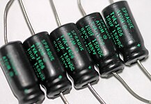


Aluminum electrolytic capacitors with liquid electrolytes have different designs, which come from the requirements of the user for a certain mounting option or from electrical boundary conditions, see pictures above from left to right:
- SMD design for surface mounting on circuit boards or substrates
- Single-ended design with radial wire connections (brought out on one side) for upright installation on circuit boards
- Axial design with axial wire connections for horizontal installation on printed circuit boards
- Snap-in design with self-locking pin connections and high current carrying capacity for standing installation on circuit boards
- Power design with screw connections for high current carrying capacity
Another excellent property of aluminum electrolytic capacitors is the variety of sizes they offer. The easy processability of the basic material aluminum enables this adaptability. The scope of different sizes ranges from miniature sizes with only 3 mm × 5 mm (DxH) to large power electrolytic capacitors with screw connections with cup dimensions of 90 mm × 210 mm.
history
origin

The phenomenon that you can use an electro-chemical process to create a layer on aluminum that allows an electric current to pass in only one direction, but blocks the current in the other direction, was discovered in 1875 by the French researcher Ducretet . Because of this effect as an "electric valve", he gave metals with this property the nickname valve metal . In addition to aluminum , tantalum , niobium , this also includes manganese , titanium , tungsten and others.
Since the oxide layer blocking on one side has a very high dielectric strength even with very thin layers, Charles Pollak , born Karol Pollak, had the idea in 1896 to use this layer as the dielectric of a polarized capacitor in a DC circuit. As a manufacturer of accumulators , Pollak had extensive knowledge of chemistry in addition to his physical knowledge. He combined the idea of the polarized capacitor with his knowledge that the oxide layer in an alkaline or neutral electrolyte remains stable even when the current is switched off. He put these two findings together and developed one from them:
" Liquid capacitor with aluminum electrodes, characterized in that an alkaline or neutral solution is used as the electrolyte and the aluminum plates are provided with a uniform insulating layer by special treatment (pickling and shaping with a weak current) before use. "
In 1896, the scientist Charles Pollak in Frankfurt was granted the patent (DRP 92564) for this idea , which became the basis for all later electrolytic capacitors. Pollak, who was later also called the Polish Edison, used it to construct new types of capacitors which, due to the very thin electrically blocking aluminum oxide layer on the anode, achieved a very high capacitance between the aluminum anode and the electrolyte solution as the cathode. The new capacitors achieved a specific capacitance that by far exceeded all capacitors known at the time, such as paper capacitors or glass capacitors .
First designs

The first electrolytic capacitors manufactured according to the Pollak patent were used at the beginning of the new century in Germany to suppress the 48 V DC voltage of telephone systems in order to reduce the interfering noises of the relays and the humming noises of the power generator on the 48 V DC line. The advantage of these capacitors was that, based on the realized capacitance value, they were not only considerably smaller, but also cheaper than the paper capacitors of the time. The structure of these "electrolytic capacitors" had little resemblance to today's designs and is more reminiscent of the structure of batteries. They consisted of a metal box which was filled with a borax electrolyte and in which a folded sheet of aluminum was installed as an anode floating freely. The metal cup then simultaneously served as a cathode connection via the electrolyte. If a DC voltage was applied to the anode, the oxide layer formed on the aluminum sheet. This construction was used until the 1930s and gave its name to the so-called "wet" electrolytic capacitors at that time. “Wet” in the sense that the electrolyte could be heard by shaking it, but also in the sense that it contained a lot of water.

With the development of radio technology in the early 1920s from detector receivers to radios with tube amplifier circuits, the need for inexpensive capacitors for larger capacitance values of 250 to 500 volts to smooth the "ripple voltage" caused by rectification increased from the early 1930s. The basic idea of liquid capacitors, in which the outer cup formed the cathode connection, was not initially deviated from. However, since smaller CV values were required, smaller round beakers which were filled with the liquid electrolyte and whose outer beaker wall was also the cathode connection could be used. Even then, it was considered that the capacity could be increased by increasing the electrode area. The endeavor to increase the capacity of these beakers by enlarging the anodes led to adventurously shaped anode shapes.
Invention of the cathode foil

Samuel Ruben is considered the father of all modern aluminum electrolytic capacitors. In 1925, as a partner of Philip Mallory, the founder of the battery manufacturer now known as Duracell , in 1925 he submitted a patent for a pioneering idea for a novel "Electric Condenser". The Rubens electrolytic capacitor adopted the technique of layered construction with several stacked anodes from the mica capacitors . To create a stacked capacitor package, he added a separate aluminum foil to each anode, which he separated with a layer of paper as mechanical protection against direct metallic contact with the anode. He conducted the second aluminum foil, later called "cathode foil", as well as the anodes , each with a contact strip to the outside, where they were combined as connections. The entire block was saturated with a special, anhydrous electrolyte. With this construction, the housing previously used as a cathode connection no longer had an electrical function. With the new cathode foil, the path that the ions had to cover in the electrolyte was considerably reduced. This reduced the electrical losses (ESR) by a factor of 10 from about 30 ohms to about 3 ohms.
With the invention of the “cathode foil” together with the gel-like water-free electrolyte, which was called “dry” in the sense of anhydrous, these capacitors became known as “dry electrolytic capacitors”.

With this and shortly afterwards (1927) the invention of wrapped foils with a paper interlayer by Alfred Heckel in Berlin, the construction volume of the electrolytic capacitors became considerably smaller and cheaper, which contributed to the fact that the new radio equipment became affordable. With this new construction of the "dry" electrolytic capacitor, the actual spread of the "electrolytic capacitors" began.
Start of mass production
The success story of electrolytic capacitors began with the invention of the wound electrolytic capacitor. With this “dry” (meaning “anhydrous”) and wound aluminum electrolytic capacitor, Cornell-Dubilier in South Plainfield, NJ, USA began the first industrial series production of electrolytic capacitors in 1931. In Germany, at the same time, industrial series production began at AEG in the AEG Hydrawerk in Berlin. Due to the consistent automation, especially in the USA, the aluminum electrolytic capacitors could be made small and inexpensive enough so that the radio sets, which were new at the time, could quickly win over new groups of buyers.

When the industrial production of electrolytic capacitors began, the anode foil was roughened in order to achieve a higher capacity. First, the films were roughened in a mechanical way, e.g. B. with sandblasting. From the mid-1930s, the mechanical processes were replaced by electro-chemical etching processes, which led to a significantly higher effective surface area of the aluminum anode. Nowadays the capacitively effective anode surface with low-voltage electrolytic capacitors can be up to 200 times larger than the smooth foil and with high-voltage electrolytic capacitors with thicker oxide layers, surface enlargements up to a factor of 30 are achieved.
The time after the Second World War is associated with a further rapid development in radio and television technology , which had a major impact on the production capacity of electrolytic capacitors. Many new companies have been founded around the world, especially in Japan . Because of the large number of units, the quality of the capacitors moved into the focus of many developments. In this regard, the products often suffered from corrosion phenomena everywhere, which impaired the service life of the electrolytic capacitors. On the one hand, the etching of the anode foils was a critical process, because u. a. Chemicals containing chlorine were used. On the other hand, the borax electrolytes used at the time contained water. Both substances caused signs of corrosion with different results. Chlorine corrosion eroded the aluminum and ultimately led to a short circuit, the water-driven corrosion caused the residual current problems of the electrolytic capacitors in the early 1950s.
The chlorine problem was recognized by around the beginning of the 1960s, and purity measures were taken to reduce the residual chlorine content. The problem of water-driven corrosion, in which increased residual currents occurred after a short storage period, initially led to reforming regulations that were proposed for the capacitors to self-heal. It was only with the development of anhydrous electrolyte systems in the 1970s and the passivation of aluminum oxide with the help of so-called inhibitors containing phosphate chemicals in the 1980s that aluminum electrolytic capacitors could be manufactured with liquid electrolytes without residual current problems. These regulations and the prejudice that al-electrolytic capacitors have excessively high residual currents after storage times have been stubbornly persistent in public to this day. Because since the 1990s, aluminum electrolytic capacitors with liquid electrolytes have been manufactured as far as possible without residual current problems.
However, chlorine corrosion was also a major problem after the component placement was introduced on circuit boards, which were then cleaned. Baths with detergents containing halogen were used for this until well into the 1980s. These agents penetrated the capacitors through the sealing of the electrolytic capacitors and caused early failures due to chlorine corrosion. It was only with the ban on halogen-containing detergents for reasons of environmental protection in the 1990s that this cause of failure was reduced in the case of the Al electrolytic capacitors.
In addition to miniaturization and the development of improved electrolytes, the development of aluminum electrolytic capacitors in the period after the Second World War was shaped by the adaptation of the design to the manufacturing conditions of the device industry. With the introduction of printed circuit board assembly with predetermined grid spacings in the early 1960s, the axial, horizontally installed designs were replaced by radial, upright designs (single-ended). Larger aluminum electrolytic capacitors, so-called “power electrolytic capacitors”, have also adapted to PCB assembly in terms of the design of the snap-in electrolytic capacitors. Due to the shape of their connection pins, they offer a firm hold on a circuit board after they have been fitted. Surface mounting technology then led to SMD designs in the 1980s. The "single-ended" design proved to be particularly adaptable. Because the round, "vertical chip electrolytic capacitors" (V-chips) are basically nothing more than radial electrolytic capacitors, the support and connections of which have been modified for surface mounting.
A particularly striking property of aluminum electrolytic capacitors is also the variety of sizes on offer, which has developed over these years. The easy processability of the basic material aluminum enables this range, which is unique in the field of electrical components. The scope of different sizes ranges from miniature sizes with only 3 mm × 5 mm (DxH) to large power electrolytic capacitors with screw connections with cup dimensions of 90 mm × 210 mm. At the same time, more and more series for industrial applications with longer service life, lower ESR values or higher temperature resistance have been developed and brought onto the market in these years. This large variety of sizes and series of aluminum electrolytic capacitors with liquid electrolytes is today (2016) a characteristic of the capacitors' adaptability to the most varied of requirements.
Development of new electrolyte systems
New solid electrolytes

A liquid electrolyte is always associated with relatively high internal losses, a relatively high ESR. A reduction in the ESR to improve the properties of the capacitor in the circuit has therefore always been a goal in the development of new electrolytic capacitors since the 1960s.
The development of tantalum electrolytic capacitors in early 1950 with a solid electrolyte made from manganese dioxide ( manganese dioxide ) therefore also influenced the development of new aluminum electrolytic capacitors. This first “solid” electrolyte had a conductivity that was 10 times better than that of liquid electrolytes. In 1964, developed by Philips, the first aluminum electrolytic capacitors with solid electrolytes ( SAL electrolytic capacitors ) came onto the market.
A completely new electrolyte at the time came from Japan. In 1983 Sanyo used it in its "OS-CON" aluminum electrolytic capacitors. These capacitors used an organic conductor, the charge transfer salt TTF-TCNQ, ( tetracyanoquinodimethane ), which offered an improvement in conductivity by a factor of 100 over wet electrolyte systems.
The ESR values of the TCNQ electrolytic capacitors were significantly reduced by the discovery of conductive polymers by Alan J. Heeger , Alan MacDiarmid and Hideki Shirakawa . The conductivity of conductive polymers such as polypyrrole or PEDOT is 100 to 500 times better than that of TCNQ and comes close to the conductivity of metals. In 1991, Panasonic launched its polymer aluminum electrolytic capacitors called "SP-Cap" . These electrolytic capacitors with polymer electrolytes achieved such low ESR values that they offered direct competition to ceramic multilayer capacitors ( MLCC ). In the cuboid SMD design, they were used a short time later in devices with a flat design such as laptops and cell phones .
The history of the development that led to the polymer electrolytic capacitor is described under polymer electrolytic capacitor # history .
New water-based electrolyte
The price pressure in the mass business with digital devices, especially with PCs, has played a major role in the latest development of new aluminum electrolytic capacitors. With the aim of reducing costs, new water-based electrolytes were developed in Japan from the mid-1980s. Water is inexpensive, is an effective solvent for electrolytes and significantly improves the conductivity of the electrolyte. But water reacts quite violently with unprotected aluminum and results in water-driven corrosion, which can ultimately lead to the destruction of the electrolytic capacitor. Therefore, the main problem in the development of the new water-containing electrolyte was to get the aggressiveness of the water towards aluminum under control with additives so that the capacitors also have a sufficiently good long-term stability.
In 1998, the Japanese manufacturer Rubycon launched the "Z series", the first capacitors that worked with an electrolyte with a water content of around 40%. Other manufacturers followed shortly afterwards. The new series were as English touted "Low ESR", "low-Impedance-", "ultra-low-Impedance-" or "High Ripple Current electrolytic capacitors" and sat down at the mass market quickly. A stolen formulation of such a water-containing electrolyte, which, however, lacked important stabilizing substances, led in the years 2000 to 2005 to the problem of massive bursting electrolytic capacitors in PCs and power supplies, which became known as " Capacitor Plague ".
Electrical characteristics
Equivalent circuit diagram
The electrical properties such as capacity, losses and inductance of real capacitors are determined according to the basic specification IEC 60384-1, which in Germany is called DIN EN 60384-1; VDE 0565-1 has been published, described with the help of an idealized series equivalent circuit diagram.

Here are:
- , the capacitance of the capacitor,
- , the equivalent series resistance or equivalent series resistance, it summarizes all ohmic losses of the component. This effective resistance is generally only called "ESR" ( Equivalent Series Resistance )
- , the equivalent series inductance or substitute series inductance, in it all inductive parts of the component are summarized, it is generally only called "ESL" ( Equivalent Series Inductivity L).
- , the parallel resistance to the ideal capacitor, which represents the residual current (leakage current) of the electrolytic capacitor.


Capacity and capacity tolerance
The usual unit of capacitance for aluminum electrolytic capacitors with liquid electrolytes is " µF ".
The capacity of an electrolytic capacitor depends on the frequency. At frequency "0", with direct voltage, an electrolytic capacitor has a capacity that corresponds to the stored charge. This capacity is called DC capacity. It is measured with a time measurement using the charge or discharge curve of an RC element . It is important when dimensioning the capacitors e.g. B. for photo flash units or for a capacitor battery for an uninterruptible power supply ( UPS ).
The measurement method for the DC voltage capacity is time-consuming and not industrially feasible. That is why the capacitance of electrolytic capacitors is measured with an alternating voltage of 0.5 V and a frequency of 100/120 Hz at room temperature of 20 ° C. The capacitance value measured at 100 Hz is about 10 to 15% lower than the value corresponding to the stored charge. In terms of the measuring frequency, electrolytic capacitors differ from ceramic and plastic film capacitors , whose capacitance is measured at 1 kHz.
The specified in the data sheets of the manufacturer capacitance value for electrolytic capacitors is the "nominal capacity C R " ( Rated capacitance C R ), also known as "design capacity". According to DIN EN / IEC 60063, it is specified in values corresponding to the E series . This nominal value is specified in accordance with DIN EN / IEC 60062 with a permissible deviation, the capacity tolerance, in such a way that no overlaps occur.


| E3 series | E6 series | E12 series |
|---|---|---|
| 10-22-47 | 10-15-22-33-47-68 | 10-12-15-18-22-27 33-39-47-56-68-82 |
| Capacity tolerance ± 20% | Capacity tolerance ± 20% | Capacity tolerance ± 10% |
| Code letter "M" | Code letter "M" | Code letter "K" |
The actual measured capacitance value must be within the tolerance limits at room temperature.
The capacity of an aluminum electrolytic capacitor with liquid electrolytes is frequency and, above all, temperature dependent: the capacity decreases sharply with increasing frequency and with decreasing temperature. Capacitors in the "low-voltage range" (≤ 100 V) show greater changes than capacitors in the "high-voltage range" (> 100 V). This is due to the size and number of pores in the etched anode foils. In electrolytic capacitors with lower nominal voltages, the anodes have significantly smaller and more pores than in electrolytic capacitors with higher voltages. At low temperatures, the charge carrier mobility of the ions in the liquid electrolyte decreases and no longer penetrates into all pores to the end of the pores. The capacity decreases. At high temperatures, increasing charge carrier mobility has the opposite effect. This effect is more pronounced in anode foils for lower voltages than in those for high voltages.
nominal voltage
The dielectric strength of aluminum electrolytic capacitors is the formation, with the aluminum oxide layer is produced, specifically prepared for the desired rated voltage of the capacitor, the " nominal voltage U R ", also called " Rated voltage U R " ( Rated voltage U R called), the DC voltage , which may be applied continuously at any temperature within the rated temperature range T R "( Rated temperature T R ). The sum of a constant DC voltage applied to the capacitor and the peak value of a superimposed AC voltage must not exceed the nominal voltage specified for the capacitor. A permanent excess the specified nominal voltage will destroy the capacitor.
The specification of a so-called " Category voltage U C " ( Category voltage U C ), that is the maximum DC voltage that may be constant at any temperature within an increased category temperature range T C "( Category temperature T C ), as it is with tantalum Electrolytic capacitors are specified with solid electrolytes, is unusual for aluminum electrolytic capacitors with liquid electrolytes.
The operation of aluminum electrolytic capacitors with a voltage lower than the specified nominal voltage is permissible and has a positive influence on the expected failure rate.
Peak voltage
For safety reasons, electrolytic capacitors are formed with a higher voltage than just the nominal voltage. Therefore, they can during the operation for a short time for a limited number of cycles of a so-called " peak voltage U S " ( surge voltage U S ) are exposed. The peak voltage is the maximum voltage value that is applied during the entire operation of the capacitors via a protective resistor of 1 kΩ or RC = 0.1 s with a frequency of 1000 cycles with a dwell time of 30 seconds and a pause of five minutes and 30 seconds without visible damage or a capacity change of more than 15%.
The permissible peak voltage is specified in DIN / EN IEC 60384-1. For aluminum electrolytic capacitors up to 315 V it is 1.15 times, for aluminum electrolytic capacitors> 315 V it is 1.1 times the nominal voltage.
Transients
Transients are fast, mostly low-energy surge peaks. In aluminum electrolytic capacitors with liquid electrolytes, the limited mobility of the ion charge carriers means that steep voltage edges are dampened. These electrolytic capacitors have a behavior towards transients that is similar to the behavior of Zener diodes and attenuates voltage peaks. This behavior only applies to low-energy transients and depends on the size of the capacitor. A general specification for this cannot be given.
Polarity reversal, reverse polarity

Aluminum electrolytic capacitors are polarized capacitors, the anode of which must be operated with a positive voltage compared to the cathode. As an exception, bipolar electrolytic capacitors are to be considered, which are constructed with two anode foils arranged with opposite poles.
Al electrolytic capacitors with liquid electrolytes are designed with a cathode foil as a power supply to the electrolyte. This cathode foil is provided with a very thin, natural air oxide layer. This oxide layer has a low temperature-dependent dielectric strength of about 0.6 V at higher temperatures up to about 1.5 V at room temperature. Therefore, aluminum electrolytic capacitors with liquid electrolytes can be loaded with very low alternating voltages, e.g. B, for measuring the capacitance according to the applicable standard with an AC voltage of 100 Hz with 0.5 V.
If a polarity reversal voltage greater than 1.5 V is applied to the electrolytic capacitor, an oxide layer is first built up on the cathode foil, which is then connected as the anode, by anodic oxidation according to the applied voltage. This is associated with gas formation ( hydrogen gas ), a pressure build-up in the capacitor and a weakening of the dielectric strength of the anode oxide.
It is now a question of the connection of the capacitor, whether the rising gas pressure leads to the beaker bursting or whether the weakening of the anode oxide leads to a breakdown and thus a short circuit . If the circuit is high-resistance, the capacitor will most likely fail due to the rising gas pressure, which will result in the valve opening or the cup bursting. If the series resistance is low, a short circuit is more likely. In any case, permanently exceeding the value of the polarity reversal voltage of around 1.5 V at room temperature will destroy the capacitor.
The bursting of an electrolytic capacitor can be quite spectacular. For this reason, the cups of the capacitors up to 18 mm in diameter have valves in the form of predetermined breaking points in the aluminum housing. Larger electrolytic capacitors have special valves to reduce the risk.
To minimize the risk of incorrect polarity when equipping, all electrolytic capacitors are marked with a polarity mark, see # polarity markings .
Impedance Z and equivalent series resistance ESR
The mathematical description of these terms, taking into account the special features that apply to electrolytic capacitors in the specification in the respective data sheets, see electrolytic capacitor # impedance Z and equivalent series resistance ESR

A special feature of aluminum electrolytic capacitors with liquid electrolytes is their relatively high specific capacitance compared to other capacitor families. Associated with the large capacitance values are low impedance values even at relatively low frequencies in the range from 50/60 Hz to a few MHz. This means that aluminum electrolytic capacitors have relatively good screening properties in this frequency range due to their large capacity. The impedance and the ESR are therefore, in addition to the capacitance, the most important electrical parameters for assessing the properties of electrolytic capacitors in power supplies for electronic circuits, for which electrolytic capacitors are particularly suitable.
The impedance Z is specified in the data sheets of electrolytic capacitors as an impedance without a phase angle. According to the applicable standard, the measurement frequency of the impedance is 100 kHz. The impedance value measured at 100 kHz usually corresponds to the 100 kHz ESR value.


The impedance and the ESR are frequency and temperature dependent. They decrease with increasing frequency and temperature. Electrolytic capacitors with liquid electrolytes have a Z / ESR value that is roughly 10 times higher at low temperatures (−40 ° C) than at room temperature. Capacitors with solid electrolytes, on the other hand, have a significantly lower temperature dependency with a factor of about 2 and an almost linear ESR curve over the entire specified temperature range. The adjacent pictures show some typical impedance curves depending on the frequency for "wet" aluminum and polymer electrolytic capacitors with different capacitance values as well as a typical impedance curve depending on the temperature.
In the ESR all losses of the capacitor add up. These losses include the losses in the oxide layers of the anode and cathode, the supply and discharge losses through the contacting of the connections, the dielectric losses in the dielectric and the conduction losses in the electrolyte. The electrolyte is of particular importance here. Solid electrolytes have a significantly better conductivity than all liquid electrolytes, which is why polymer electrolytic capacitors have much lower ESR values. But the structure of the anode also influences the ESR. A high specific capacitance of an electrolytic capacitor, which can be achieved with very high roughness of etched Al foils, has a higher impedance and a higher ESR than capacitors with a slightly roughened anode and a lower specific capacitance due to the thinner current paths in the anode pores.
However, the ESR is also influenced by the frequency and the temperature. Because with increasing frequency, the depth of penetration of the ions of the electrolyte into the pores of the roughened anode decreases, so that the conduction losses in the electrolyte decrease with increasing frequency. At the same time, the conductivity of the liquid electrolyte improves with increasing temperature. This means that the load on a capacitor with a given ripple current decreases with increasing frequency of the current and increasing temperature, because less heat is lost due to the decreasing ESR.
Current carrying capacity
Ripple current

An alternating voltage superimposed on the direct voltage and applied to a capacitor causes charging and discharging processes in it. This results in an alternating current, the ripple current I R ( ripple current ) is called. It flows as RMS on the ESR of the capacitor and is frequency-dependent electrical losses P V el result

which heat it up from the inside and lead to a temperature increase. This internally generated temperature is added with any other heat sources to the operating temperature of the condenser, which then differs from the ambient temperature by the value ΔT .
This temperature difference ΔT is dissipated as thermal power loss P V th through thermal conduction , radiation and convection via the surface A and the heat transfer resistance β of the capacitor to the environment.

If the electrical losses P V el and the thermal power loss P V th are in thermal equilibrium, the temperature difference between the capacitor and the environment is calculated from:

Typically, the data sheet value of the ripple current leads to a temperature difference between the capacitor winding core and the surrounding area of 10 K for 85 ° C electrolytic capacitors, 5 K for 105 ° C electrolytic capacitors or 3 K for 125 ° C electrolytic capacitors. Because of the temperature gradient from the core to the cup of the capacitor, this temperature difference can only be measured as the core temperature in the coil.
The core temperature of the capacitor ultimately determines the evaporation rate of the electrolyte and thus the service life of the electrolytic capacitor. It is specified in such a way that the temperature increase caused by the specified ripple current is part of the specification. The ripple current can therefore flow continuously through the capacitor during the entire operating time, the calculated service life, even at the maximum temperature. Smaller ripple currents than specified have a positive effect on the service life of the capacitors. Appropriate measures such as B. special positioning on the circuit board or forced cooling, the heat dissipation can be forced, which can have a positive effect on the life of the capacitors.
The ripple current is always an effective value of a current of any frequency and waveform. The data sheet value is specified as a sinusoidal current mostly at 100 Hz or at 10 kHz and the maximum temperature. In the case of non-sinusoidal ripple currents and other frequencies, the current has to be broken down into its sinusoidal components using Fourier analysis , since the ESR is frequency-dependent . These can then be added as a square.

This also applies to periodically occurring pulse loads, where the individual pulse current can be significantly higher than the specified ripple current.
Because the value of the ripple current specified in the data sheets is frequency-dependent; it decreases with increasing frequency, a 100 Hz value specified in the data sheet can be converted for higher frequencies; it increases for higher frequencies. For example, the 10 kHz value is about 30 to 40% greater than the 100 Hz value. Corresponding correlation factors are specified by the respective manufacturer.
The ripple current specified in the data sheets must not be exceeded within the nominal temperature range without forced cooling. A higher ripple current than specified can lead to the boiling point of the electrolyte being exceeded, which destroys the capacitor. Ripple currents higher than specified are only permitted with forced cooling.
Charge, discharge, inrush current
Aluminum electrolytic capacitors with liquid electrolytes are relatively insensitive to high current peaks ( current surge ) during charging or discharging processes because of the limited mobility of the ion charge carriers . Also high inrush currents ( inrush current ) usually do not cause failures. However, when these currents are loaded, the specified maximum ripple current must not be exceeded.
Damage due to steep di / dt current flanks, as can occur with film capacitors, does not occur with aluminum electrolytic capacitors. A change in the structure of the oxide, which occurs, for example, in tantalum electrolytic capacitors and can lead to short circuits, does not occur with Al electrolytic capacitors. It is therefore not necessary to limit peak inrush currents that occur rarely, provided that the electro-thermal load ( I 2 R ) in the cross-sections of the connections is not exceeded. With large screw terminal electrolytic capacitors, a maximum current of 50 A is sometimes specified because of this thermal load on the connections.
Residual current, leakage current


A special feature of electrolytic capacitors is the so-called residual current ( English leakage current ) I leak past also, leakage current called. The residual current of an electrolytic capacitor is the direct current that flows through it when a direct voltage of the correct polarity is applied. The residual current is caused by flaws due to impurities in the oxide of the dielectric, breaks in the oxide that occur during soldering and, if necessary, by weakening of the oxide that occurs due to chemical dissolution processes during storage without tension. The residual current is dependent on capacity, voltage, time and temperature. Due to the self-healing effects in aluminum electrolytic capacitors with liquid electrolytes, the residual current usually decreases the longer the capacitor is connected to voltage.
The residual current is usually specified by multiplying the nominal capacitance value C R and the nominal voltage U R , to which a small fixed value is often added. For example

This value must be adhered to after the prescribed measuring time of, for example, 2 or 5 minutes. It gets smaller and smaller the longer the capacitor is on. After an operating time of around 1 hour, there will be an operating residual current that is usually well below the data sheet value.

The residual current of an electrolytic capacitor depends on the voltage and temperature. At 85 ° C it can reach about four times the value compared to the 20 ° C value. On the other hand, the residual current will only reach about 50% of the 20 ° C value if the operating voltage is about 30% below the nominal voltage.
Aluminum electrolytic capacitors with liquid electrolytes had problems with high residual currents after storage times until the 1960s. The reason for this was on the one hand corrosion , caused by contamination with chlorine in the production of roughened anode foils. On the other hand, the aggressiveness of water-containing electrolyte systems was responsible for a weakening of the oxide layers. These problems resulted in proposals for reforming such as, for example, applying the nominal voltage via a current limiting resistor of 1 kΩ for about 1 hour.
Modern aluminum electrolytic capacitors with electrolytes based on organic solvents can nowadays be manufactured and delivered without residual current problems after storage without voltage. Some manufacturers even specify no-tension storage times of up to 10 years without reforming.
It looks a little different with electrolytic capacitors with electrolyte systems based on high water content electrolyte systems. With these " low-ESR " or " low-impedance " -Elkos, the aggressiveness of the water is difficult to control with a water content of> 40%. The spread of measured residual current values of a large number of tested electrolytic capacitors after longer storage times is very large. Such electrolytic capacitors are not suitable for applications in which low, constant residual current values are required. However, a high residual current value with these electrolytic capacitors is already strongly reduced to a low, "normal" value after a short period of operation.
Although the residual current values of today's electrolytic capacitors are quite small, they are significantly higher than the currents through the insulation resistance of plastic film and ceramic capacitors. Therefore, Al electrolytic capacitors are not suitable for circuits such as B. sample-and-hold circuits , precise time measurements or stabilization of high-resistance voltage sources.
Dielectric absorption (recharge effect)
The dielectric absorption ( latin absorbere "aspirate, absorb") describes the dielectric properties of a non-conductor as a function of frequency . In the case of aluminum electrolytic capacitors, the effect is responsible, on the one hand, for the dielectric losses in AC voltage operation and, on the other hand, for the occurrence of a voltage on the capacitor after switching off and discharging. This effect is also called the reload effect.
The voltage that can arise at the connections of electrolytic capacitors after switching off and discharging due to dielectric relaxation can reach 10 to 15% of the voltage previously applied. The "recharged" voltage can last for months with the high insulation resistance of the aluminum oxide in the electrolytic capacitors. Unloading with subsequent reloading can be repeated several times.
The reloading effect can under certain circumstances lead to relatively high voltages, which can endanger the environment. This voltage, which can be 50 V with 400 V electrolytic capacitors, can damage semiconductors or cause sparks during installation. This effect is also undesirable in measuring circuits, since it leads to incorrect results. Larger aluminum electrolytic capacitors are therefore usually transported or delivered with a short-circuit clip over the connections.
Notes on operation
reliability
The reliability of a component is a property that indicates how reliably ( failure rate ) this component will fulfill its respective function in a time interval ( service life ). It is subject to a stochastic process and can be described qualitatively and quantitatively; it is not directly measurable.
Failure distribution (bathtub curve)

The temporal behavior of failures in a batch of similar components is shown as a so-called bathtub curve, which has three areas: 1) area of early failures, 2) area of constant failure rate (random failures) and 3) area of wear failures (change failures). With all electrolytic capacitors, early failures are mostly removed at the manufacturer's facility during formation. In the area of the constant failure rate, only "random failures" occur. This range applies to the specification of the failure rate λ . The range ends when wear failures occur (change failures). As a result, area 2), the area of random failures, corresponds to the calculated service life of aluminum electrolytic capacitors with liquid electrolytes.
Failure rate
The failure rate is a statistical value about the probable functionality of components in a time interval. It cannot be measured directly and is determined via the failures in the production-accompanying endurance test , in which the components are tested with the applied nominal voltage at the upper nominal temperature. Both total failures ( short circuit , interruption) and change failures (exceeding characteristic value limits) are rated as failures .
The failure rate λ is obtained by dividing the failures C that have occurred by the number of test objects n multiplied by the test time t:

It indicates how many capacitors will fail on average in a unit of time and is given in 1 / time, i.e. failure per unit of time. As a statistical value, the failure rate is still at a confidence level ( confidence interval , confidence level subject), usually 95%. If the failure rate is constant, then the reciprocal value of the failure rate is the mean operating time until failure MTTF ( Mean Time To Failure ) and is used to calculate a survival probability for a desired device service life in combination with other components involved.
The failure rate λ depends on the temperature, the applied voltage, various environmental influences such as humidity, shocks or vibrations and the capacitance of the capacitor. Therefore, the failure rate determined in the continuous voltage tests is converted to reference conditions. According to IEC [DIN EN] 61709, it is specified as the reference failure rate failure rate λ ref (FIT) with the unit FIT ( Failure In Time ) under the following reference conditions:
- Failure rate λ ref (FIT) in “n failures per 10 9 h at 40 ° C and U = 0.5 or 0.8 U R ”.
The unit FIT indicates the number of failures that occur in 10 9 hours: 10 FIT are 10 failures per 10 9 hours or 10 failures per 114,000 years or 1 failure per 11,400 years. Users can calculate the individual failure rate for their own operating conditions from the respective reference failure rates of the manufacturer with the help of so-called acceleration factors. There are also different models such as the one according to MIL-HDBK-217 F or according to Bellcore / Telcordia. Some electrolytic capacitor manufacturers also provide their own calculation models, e.g. B. Vishay and Kemet.
The published failure rates for aluminum electrolytic capacitors with nominal voltages from 6.3 to 160 V show failure rates in the range from 1 to 20 FIT and for electrolytic capacitors with nominal voltages from> 160 to 550 V failure rates in the range between 20 and 200 FIT. These values are within the normal range for electronic components .
In order to determine these already very low failure rates in the continuous voltage tests accompanying production, billions of component test hours are required. This requires a large amount of personnel and considerable financing. Even smaller numerical values can no longer be achieved with the help of tests. That is why failure rates are often mentioned that come from failure feedback from customers. These "field failure rates" are usually significantly lower than the failure rates determined in the tests. They are in the range between 0.5 and 20 FIT.
Failure rates are used to calculate the probability of survival of a device in combination with other components involved. For example, a flashing lamp consists of
- 20 resistors: 20 x 0.1 FIT
- 3 transistors: 3 x 1 FIT
- 2 electrolytic capacitors: 2 x 0.5 FIT
- 1 battery: 200 FIT.
The total failure rate is the sum of all failure rates and thus 206 FIT. The average operating time of the device is 554 years, provided the battery is changed regularly. But the electrolytic capacitors have a time limit in the range of the constant failure rate due to drying out. Then wear failures occur, depending on the series and operating conditions, they are likely to begin after a few decades. After 554 years all electrolytic capacitors have probably dried up. This example clearly shows that the average operating time of the device, calculated with the failure rates, can never be longer than the calculated life of the aluminum electrolytic capacitors used.
lifespan
The term “service life” in connection with electronic components is used when the components of the component experience physical or chemical changes during operation that lead to changes in the electrical parameters and the occurrence of wear failures. This is the case with aluminum electrolytic capacitors with liquid electrolytes. Here, in the course of operation, signs of aging occur due to evaporation, which are temperature-dependent and partly also voltage-dependent. In connection with this, the electrical parameters of the capacitors change over time, which ultimately leads to change failures and the functionality of the capacitors is only limited. The time until change failures occur is the “service life” or “ useful life ” ( useful life, load life, service life ) of these capacitors.
This service life is the time until a certain percentage of failures in a batch is reached by exceeding electrical parameters. This means that the “end of service life” of this batch has been reached. At the same time, it is the end of the range of the constant random failure rate. This limited service life by changing the characteristic values can u. It may be shorter than the mean operating time determined by the MTTF until a random failure occurs.
The service life of aluminum electrolytic capacitors with liquid electrolytes is determined in production-accompanying time-lapse endurance tests with the nominal voltage applied at the upper nominal temperature. Typically, the capacitance and the residual current decrease over the course of the test, while the equivalent series resistance ESR and the impedance increase. The change failures occur when defined change limits are exceeded. On the one hand, these are total failures (short circuit, interruption) and, on the other hand, according to IEC / DIN / EN 60384-4-1, for example, a reduction in capacity by more than 30% and an increase in the ESR or the loss factor by more than a factor of 3 compared to the initial value The random failures (total failures) during the service life are mostly negligible.

The picture on the right shows the changes in the characteristic values of aluminum electrolytic capacitors with liquid electrolytes due to evaporation of the electrolyte in a tested batch during a 2000 h continuous voltage test at 105 ° C. The individually different drying rates can also be clearly seen due to the spread of the batch values at the end of the test.
In the case of aluminum electrolytic capacitors with liquid electrolytes, the limited service life due to evaporation and chemical decomposition can be significantly influenced by the design (sealing, type of electrolyte, purity of the materials). Due to a hermetic seal in tantalum electrolytic capacitors with liquid electrolytes, for example, there is no definition of the service life of these electrolytic capacitors. For cost reasons, this design is not available with Al-Elkos. With the best possible sealing methods available with Al electrolytic capacitors, diffusion cannot be completely prevented, so that the life of the electrolytic capacitor is limited. The total diffusion rate is primarily determined by the temperature of the capacitor. The different electrolytes play a further role. In the case of electrolytic capacitors with water-containing electrolytes, there is also a slight loss of electrolyte due to a slightly higher residual current. The entire process of dehydration can be demonstrated not only by changing electrical parameters but also by weight loss.
The specification of the service life of aluminum capacitors with liquid electrolytes is made by combining the test time in hours and the test temperature, e.g. B. "5000 h / 85 ° C", "2000 h / 105 ° C" or "1000 h / 125 ° C". This specification specifies the minimum service life of the capacitors that they are likely to achieve at the continuously prevailing maximum temperature and applied nominal voltage.
This specification also includes that the capacitors can be loaded with the nominal ripple current value. The heating of the capacitor of 3 to 10 K, depending on the series, caused by the ripple current through heat losses, is normally taken into account by the manufacturer by means of safety reserves when interpreting the results of his continuous voltage tests. A test with an actually flowing ripple current is not affordable for any manufacturer.
Since the chemical changes in the electrolyte over time depend on the temperature and the applied voltage, the service life is temperature and voltage dependent. Operating the capacitors at a lower temperature and voltage than the test conditions will result in a longer life of the capacitors. The estimation of this service life extension for aluminum electrolytic capacitors with liquid electrolytes is mostly described in the data sheets of many manufacturers worldwide using the so-called 10 degree rule ( Arrhenius rule , RGT rule ):

- L x = service life to be calculated
- L Spec = Specified service life (useful life, load life, service life)
- T 0 = upper limit temperature (° C)
- T A = ambient temperature (° C),
With the help of this formula, which doubles the service life per 10 K ( ° C ) temperature reduction, the service life of the capacitors can be roughly estimated at any operating temperature, whereby the influence of the voltage load is not taken into account. According to this formula, the expected service life of a charge of 2000 h / 105 ° C electrolytic capacitors, which are operated at only 45 ° C, can be estimated at 128,000 hours or around 15 years. If the operating temperature were to rise to 65 ° C and the same service life should be achieved, then electrolytic capacitors of a different series with the specification of either 8000 h / 105 ° C or 2000 h / 125 ° C would have to be used.

The 10-degree rule only applies if it is confirmed by the respective capacitor manufacturer, because some manufacturers definitely specify different service life calculation formulas, sometimes even different formulas for different series, or different service life diagrams from which the Elko service life can be read for different loads. In all of these " calculations " of a service life, however, it should be noted that the calculation only results in an " estimated value " which is actually only the minimum value of the expected service life of a batch of capacitors of the same type.
In general, for aluminum electrolytic capacitors with liquid electrolytes, it can be stated that by selecting appropriately specified series, both shorter service lives for lower requirements and longer service lives at higher temperatures can be achieved. But even after the end of the service life is exceeded by continued operation of the capacitors, the circuit does not face any immediate danger. With today's high degrees of purity in the production of electrolytic capacitors, a short circuit is not to be expected even after the change limits have been exceeded at the end of the service life and drying out progresses. However, due to deterioration in the storage capacity or the sieve property z. B. problems with the interference suppression or the like result.
Shelf life
Up until the 1960s, aluminum electrolytic capacitors with liquid electrolytes had problems with high residual currents, both during delivery and during operation. This was due to two different types of corrosion , chlorine corrosion and water-driven corrosion. Based on this behavior, so-called “reforming regulations” were recommended, which included that the capacitors should be connected to nominal voltage for a few minutes up to 1 hour via a current limiting resistor before they are put into operation. This reforming has not been necessary since the 1980s at the latest. Avoiding contamination of the lower parts with chlorine as well as controlling the chemical aggressiveness of the water against the anode oxide layer has been "state of the art" since then. Residual current problems after voltage-free storage within one year or during operation do not normally occur with electrolyte systems in today's production.
The situation is somewhat different for aluminum electrolytic capacitors with liquid electrolytes after long periods of storage without voltage. In particular, the amount of water as a constituent of the electrolytes ensures different chemical sensitivity of the oxide layer after prolonged storage. With regard to the storage behavior, the electrolytic capacitors can be roughly divided into three groups due to the different electrolytes:
- Capacitors with high water content electrolytes (> 40%, the so-called low ESR capacitors) can be stored for about 1 to 2 years
- Capacitors with standard electrolytes based on borax or ethylene glycol with about 5 to 20% water can be stored for at least 2 years
- Electrolytic capacitors with anhydrous solution electrolytes based on, for example, γ-butyrolactone can be stored for up to 10 years
In this sense, storable means that the capacitors soldered into a circuit can be switched on after the specified de-energized storage time without any further precautionary measures. The shelf life of electrolytic capacitors is checked with the help of a hot storage time test ( shelf life test ), usually 1000 hours, without applied voltage at the upper nominal temperature. This test accelerates any possible aggressive chemical processes that can lead to a high residual current and prevents self-healing through reforming. The hot storage time test is a good indicator of the chemical compatibility of the electrolyte system with respect to the materials and the high degree of purity during manufacture. Provided that the chemical processes that act on the anode oxide layer also follow a 10-degree law, as in the case of estimating the capacitor life, a successful shelf life test of 1000 hours at 85 ° C would result in a voltage-free storage time at 25 ° C of around 7 years.
However, it should also be pointed out here that after 2 years of storage, the solderability of the connections can become problematic due to oxidation of the tin-plating.
With electrolytic capacitors with solid electrolytes, the residual current problem does not occur after storage times.
Causes of failure, self-healing and application rules
Causes of failure

Aluminum electrolytic capacitors with liquid electrolytes have a negative public image in terms of their quality. This is in contrast to the experiences in the industry that consider these capacitors to be reliable components within their calculated life. The negative image of the electrolytic capacitors has historical reasons and may also be due, among other things, to the fact that failed electrolytic capacitors are easy to recognize in devices. This is not the case with other electronic components. This appearance is deceptive, the Elko quality from well-known manufacturers is nowadays well within the scope of the usual, very high reliability of electronic components.
The historical reasons go back to the 1960s and lie in the lack of knowledge of chemical relationships at the time, but also the measurement methods that were not yet available at the time. At that time, small amounts of contamination with chlorine were the cause of increased residual currents associated with corrosion . This problem of the lower parts contaminated with chlorine has been solved since the mid-1960s. Instead, the problem of water-driven corrosion arose, which led to a reduction in the service life of the capacitors. This problem was solved in the 1980s with the introduction of so-called corrosion inhibitors. The after-effects of these problems may justify the prejudices that still exist today with regard to the quality images of the electrolytic capacitors.

The aluminum electrolytic capacitors manufactured today and used in devices meet the high quality requirements of industry in almost all areas. Occur anyway isolated on failures in the analysis of these failures, the failure causes (can failure mode ) are divided into four groups: 1) failure caused by an intrinsic chemical or physical process, 2) failures in the Elko development or production were caused by the manufacturer, 3) failures that were caused during device development or manufacture and 4) failures that occur during use by the device user. While points 2) to 4) are ultimately due to human error, if there is an inherent cause of failure, despite the best possible control of all manufacturing processes, sudden errors in operation cannot be completely ruled out.

Aluminum electrolytic capacitors with liquid electrolytes do not have an inherent failure mechanism that can lead to sudden failure, provided that the respective electrolyte is chemically neutral to the aluminum and its oxide. However, in these "wet" electrolytic capacitors, the electrical parameters change due to slow evaporation of the electrolyte, so that the service life of these electrolytic capacitors is limited in time.
Manufacturer-related causes of failure may arise. a. due to ignorance of chemical reactions during development, improper manufacturing, poorly maintained tools, inadequate quality assurance or the use of incorrect parts. But nowadays at least all major manufacturers of electrolytic capacitors have a well-structured quality assurance system that carefully monitors all steps from development through all process steps to the end product. The manufacturer's flow charts for the types of errors in the process steps demonstrate this high quality standard.
But quality monitoring does not work in all cases. The system failed in the incident known as Capacitor Plague . In the years 2000 to 2003, some Taiwanese manufacturers used a stolen, poorly composed electrolyte. The advantage of this electrolyte was its low price combined with low ESR values. B. with the same ripple current load smaller and thus significantly cheaper electrolytic capacitors could be produced. This "wrong" electrolyte caused water-driven aluminum corrosion with unchecked formation of aluminum hydroxide and hydrogen gas and led to massive failures of electrolytic capacitors from these manufacturers until around 2007. The combination of a lower price on the part of the manufacturer and a lower purchase price on the part of the user with simultaneous failure of safeguarding the long-term quality led to this catastrophe. In the picture at the top right you can see such aluminum electrolytic capacitors , so-called "bad caps" , which are prematurely connected by corrosion with internal overpressure and a subsequent opened predetermined breaking point in the cup. The brownish incrustation on the electrolytic capacitor is leaked and dried electrolyte, see picture above right.

A typical cause of failure caused by device manufacturers are those failures that occurred in the 1970s and 1980s. These failures were caused by the washing of assembled circuit boards with halogen-containing detergents during the manufacture of devices. Chlorine molecules were able to penetrate the electrolytic capacitor seal and caused aluminum corrosion of the electrode foils. After the chlorinated hydrocarbons were banned in industry for reasons of environmental protection at the end of the 1980s , these failures no longer occur.

An example of failures that can occur during device production can be seen in the picture on the right. Radial electrolytic capacitors are quite sensitive to mechanical loads on the connections. In the case shown, mechanical pressure on a connection during manual assembly of a printed circuit board caused the connection in the coil to be torn out, resulting in a loose contact.
Elko failures caused by the device user during use are also known to be premature failures. As an example, which can overclock of processors are used, with the aim of a higher processing power to achieve. This results in an increase in the ripple currents in the device's power supply unit. The life expectancy of the power supply electrolytic capacitors can sometimes decrease significantly due to the associated increased heat development.
But not everything that is noticeable when looking at assembled circuit boards and looks like a defective electrolytic capacitor is actually damaged. With reflow soldering , especially if lead-free solders are used, the temperature load during soldering can result in strong internal pressure in an SMD capacitor. Depending on the volume of the capacitor, the electrolytic capacitor can inflate under certain circumstances. The internal pressure is reduced over time, but the bulge can remain permanent, but this does not affect the reliability of the capacitor.
self-healing

Aluminum electrolytic capacitors with liquid electrolytes have a self-healing mechanism that kicks in in the event of spot contamination, oxide fractures or weakened oxide areas, because the electrolyte can supply the oxygen to build up a new oxide layer. This self-healing through reforming starts immediately after applying a voltage with the correct polarity. The reforming process is associated with a higher residual current, which, however, usually disappears again very quickly.
Application rules
The general rule for all electrolytic capacitors is that they must not be thermally or electrically overloaded during operation. In addition, u. U. Defects in the oxide layers have an impact on the reliability or the service life of the different types of capacitors. However, aluminum electrolytic capacitors with liquid electrolyte do not have an inherent failure mechanism. Defects in the oxide are healed by reforming when a voltage is applied. A specific application rule for these "wet" electrolytic capacitors is that a service life calculation must be carried out for the intended application.
More information
Parallel and series connection
Parallel connection of electrolytic capacitors

If, in a parallel connection of capacitors, one specimen gets a short circuit, the entire energy of all capacitors is discharged through this defect. In the case of larger capacitors, in particular larger aluminum electrolytic capacitors for higher voltages, this can lead to quite large discharge phenomena with consequential damage. Therefore, in such a case, measures should be taken to limit the short-circuit discharge current. This can e.g. B. be done by individually protecting each capacitor via an overcurrent protection device.
Series or series connection of electrolytic capacitors

A series or series connection of electrolytic capacitors results in a distribution of the total voltage across the individual capacitors connected in series, which results from the individual insulation resistances. These insulation resistances are represented by the residual current of the capacitors. In the case of different residual currents, an uneven voltage distribution results after applying a voltage, which is inversely proportional to the individual residual current and can be quite large under certain circumstances. This can u. U. the maximum permissible voltage for individual copies in the capacitor bank may be exceeded. Therefore, in particular, larger aluminum electrolytic capacitors for higher voltages, such as those required in capacitor banks for frequency converters , must be balanced with balancing resistors or with active voltage balancing with push-pull transistors.
standardization
Standardization for all electrical, electronic components and related technologies follows the rules of the International Electrotechnical Commission (IEC) , a non-profit, non-governmental organization for international standards. In Germany, these standards were initially harmonized by the VDE as DIN standards, then in the European framework as EN standards. The terminology of the electrical characteristics for fixed capacitors for use in electronic devices as well as the methods for measuring and testing these parameters are internationally standardized in the basic specification
- IEC 60384-1, Fixed capacitors for use in electronic equipment - Part 1:
which in Germany also as DIN EN 60384-1; VDE 0565-1 has appeared. In addition to this, the preferred values for dimensions and properties as well as additional test methods, applicable test severity and acceptance criteria are defined in the corresponding framework specifications for electrolytic capacitors.
- IEC / DIN EN 60384-4, aluminum electrolytic capacitors with solid (manganese dioxide) or liquid electrolytes
- IEC / DIN EN 60384-18, surface-mountable aluminum electrolytic capacitors with solid (manganese dioxide) or liquid electrolytes
- IEC / DIN EN 60384-25 - Surface-mountable aluminum electrolytic capacitors with conductive polymer solid electrolytes
- IEC / DIN EN 60384-26 - aluminum electrolytic capacitors with conductive polymer solid electrolytes
Circuit symbols
The electrical circuit symbols of electrolytic capacitors are standardized according to IEC / DIN / EN 60617-4.
Circuit symbols for electrolytic capacitors

polarized capacitor

polarized capacitor

polarized capacitor

Bipolar electrolytic capacitor


Type identification
If there is enough space, aluminum electrolytic capacitors should be labeled with the following:
- Polarity, nominal capacity, tolerance, nominal voltage, nominal temperature range, date of manufacture, manufacturer, series designation
Uncoded labeling is possible for larger components. In the case of chip capacitors, however, this is not possible because of their small size. Capacity, tolerance and date of manufacture can therefore be marked with abbreviations in accordance with IEC / DIN EN 60062.
Example of a short designation of the nominal capacity with a unit symbol (microfarad):
- µ47 = 0.47 µF, 4 µ7 = 4.7 µF, 47 µ = 47 µF
Example of a short designation of the nominal capacity with a number for the unit:
- 476
The first two digits indicate the value in picofarads, the third the number of subsequent zeros. 476 means 47 × 10 6 pF = 47,000,000 pF = 47 µF.
The tolerance is marked with a letter:
- K = ± 10%, M = ± 20%
The nominal voltage can be coded with a letter. There are no uniform rules here
The date of manufacture is often printed in abbreviated form in accordance with international standards.
- Version 1: Coding with year / week, "0708" is then 2007, 8th calendar week
- Version 2: Coding with year code / month code
- Year code: "R" = 2003, "S" = 2004, "T" = 2005, "U" = 2006, "V" = 2007, "W" = 2008, "X" = 2009, "A" = 2010, "B" = 2011, "C" = 2012, "D" = 2013, "E" = 2014, "F" = 2015, "G" = 2016 etc.
- Month code: "1" to "9" = Jan. to Sept., "O" = October, "N" = November, "D" = December
- "A5" is then 2010, May
Polarity marking
- Marking the polarity


In the case of electrolytic capacitors with liquid electrolytes , the negative pole is marked.
There are several variants for marking the polarity:
- With the axial / horizontal design , the negative pole is connected to the housing, the positive pole is insulated. There is a notch all the way around on the positive side. With older electrolytic capacitors, the negative side is also marked with a colored ring.
- With the vertical design (radial design or also called "single ended") there is a vertical minus mark on the negative side. In addition, the plus connection is longer than the minus connection for loose, unstrapped goods.
- With SMD -Elkos there is a negative mark on the visible part of the cup, usually a black bar.
In the case of electrolytic capacitors with solid electrolytes , the positive pole is generally marked.
- In tantalum capacitors in bead form the positive pole of which is indicated by a plus.
- With the axial / horizontal design , the negative pole is connected to the housing, the positive pole is insulated. There is a notch all the way around on the positive side.
- Special note : The polarity markings on electrolytic capacitors with solid electrolytes, e.g. B. in polymer electrolytic capacitors , is specific to the respective design. The negative pole is marked on cylindrical wired or cylindrical SMD electrolytic capacitors. In the case of cuboid SMD electrolytic capacitors, the positive pole is marked with a bar.
- Marking of polarity on polymer aluminum electrolytic capacitors
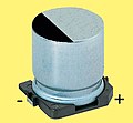
In the case of the V-chip design and the radial design, the minus connection is color-coded.
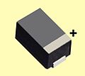
In the case of the cuboid SMD design, the plus connection is color-coded.


Applications
Typical applications for aluminum electrolytic capacitors with liquid electrolytes are:
- Smoothing and buffer capacitor for smoothing or filtering rectified AC voltages in power supplies and switched-mode power supplies
- Sifting of AC voltage components within a circuit (derivation of AC currents), for example in DC / DC converters
- Buffering DC voltage supplies in the event of load changes e.g. B. in frequency converters and uninterruptible power supplies ( UPS )
- Buffer for PFC circuits ( power factor correction , dt. " Power factor correction ")
- Coupling and decoupling of AC voltage signals, for example in low-frequency amplifiers, when there is a potential difference (level shifting). It should be noted that the electrolytic capacitors require an appropriate bias
- Energy storage, for example in electronic flash units
- Bipolar (non-polarized) electrolytic capacitors as starting capacitors for asynchronous motors
- Audio frequency or bipolar capacitors in loudspeaker crossovers
Advantages and disadvantages
Advantages:
- Very inexpensive capacitors with very high capacities per volume
- The energy storage capacity per unit volume is only exceeded by supercapacitors (double-layer capacitors)
- The high capacitance value enables the sieving of relatively low interference frequencies
- For power supplies with operating voltages> 50 V, so-called "wet aluminum electrolytic capacitors" with nominal voltages of up to 630 V are the most inexpensive solutions
- Al-Elkos can be switched without current limitation
- The liquid electrolyte makes aluminum electrolytic capacitors insensitive to transients
- The residual current drops relatively quickly to a low value due to self-healing
- By choosing an appropriate series (long service life), very long operating times are possible
- Very large variety of designs, very many providers
Disadvantage:
- Useful life / service life limited by the influence of heat. The heat can also arise from the inside through higher ripple currents
- Relatively bad behavior at low temperatures. The impedance and the ESR are about ten times higher at −40 ° C than at room temperature
- Very sensitive to mechanical damage (tension or pressure on the connecting wires)
- Very sensitive to halogens (chlorine, bromine). Even small amounts that could get inside through the seal in the event of contamination can lead to corrosion and thus to the destruction of the capacitor
- Longer voltage loads in the reverse polarity direction inevitably destroy the capacitor, usually through an explosion
market
The market for aluminum electrolytic capacitors was around US $ 3.9 billion in 2010, or around € 2.9 billion. Al-electrolytic capacitors covered around 6.5% of the number of units, that is around 90 billion units, around 22% of the value of the capacitor market.
Manufacturers and Products
| Manufacturer | Available finishes | ||||||||
|---|---|---|---|---|---|---|---|---|---|
| SMD | Radial | Axially | Snap-in | Screw connection |
Bipolar audio |
Engine start |
polymer | Polymer hybrid |
|
| CapXon, | X | X | - | X | X | X | - | X | X |
| Daewoo, (Partsnic) | X | X | - | X | - | - | - | - | - |
| CDE Cornell Dubillier | - | X | X | X | X | - | - | X | - |
| Capacitor Industries | - | - | - | X | X | - | X | - | - |
| Elna | X | X | - | X | X | X | - | X | - |
| Frolyte | X | X | X | - | X | - | - | - | - |
| Fischer & Swap | - | X | X | X | X | X | X | - | - |
| Hitachi | - | - | - | X | X | - | - | - | - |
| Hitano | X | X | X | X | - | - | - | - | - |
| Illinois Capacitor | X | X | X | X | X | X | - | - | - |
| Itelcond | - | - | - | X | X | - | - | - | - |
| Jackcon | X | X | X | X | - | X | - | - | - |
| Jianghai | X | X | - | X | X | - | - | X | - |
| Lelon | X | X | - | X | X | X | - | X | - |
| Kaimei Electronic Corp, (Jamicon) | X | X | - | X | X | X | - | X | - |
| KEMET-Evox-Rifa Group | X | X | X | X | X | - | X | - | - |
| MAN YUE, (Samxon) | X | X | - | X | X | X | - | - | - |
| Nantung | X | X | - | X | - | X | - | - | - |
| NIC | X | X | - | X | - | X | - | X | X |
| Nichicon | X | X | X | X | X | X | - | X | - |
| Nippon Chemi-Con, (NCC, ECC, UCC) | X | X | X | X | X | X | - | X | X |
| Panasonic, Matsushita | X | X | X | X | - | X | - | X | X |
| Richey Capacitor Inc. Richey | X | X | X | X | - | - | - | - | - |
| Rubycon | X | X | - | X | X | X | - | X | - |
| SUN Electronic Industry | - | X | - | - | - | - | - | X | - |
| TDK EPCOS | - | X | X | X | X | - | - | - | - |
| Vishay, (BCc, Roederstein) | X | X | X | X | X | - | - | - | - |
| Yageo | X | X | - | X | X | - | - | X | - |
See also
- Capacitor (electrical engineering)
- Electrolytic capacitor
- Tantalum electrolytic capacitor
- Polymer electrolytic capacitor
- Niobium electrolytic capacitor
- Super capacitor
- Plastic film capacitor
- Ceramic capacitor
literature
- E. Hering, K. Bressler, J. Gutekunst: Electronics for engineers and natural scientists. 6., fully act. u. exp. Edition. Springer Verlag, Berlin 2013, ISBN 978-3-642-05498-3 .
- D. Nührmann: The complete workbook electronics. Franzis, Poing 2002, ISBN 3-7723-6526-4 .
- KH Thiesbürger: The electrolytic capacitor. 4th edition. Roederstein, Landshut 1991, OCLC 313492506 .
- O. Zinke, H. Since: Resistors, capacitors, coils and their materials. Springer, Berlin 1982, ISBN 3-540-11334-7 .
- L. Stiny: Handbook of Passive Electronic Components. Structure, function, properties, dimensions and application. Franzis-Verlag, 2007, ISBN 978-3-7723-5430-4 .
- K. Beuth, O. Beuth: Components. Electronics 2nd Vogel book, 2006, ISBN 3-8343-3039-6 .
- H. Bernstein: Components of Electronics. De Gruyter Oldenbourg, 2014, ISBN 978-3-486-72127-0 .
Individual evidence
- ↑ a b CDE, series DCMC, cde.com (PDF)
- ↑ a b Jianghai, 630 V capacitors jianghai-europe.com (PDF)
- ↑ a b Jeng-Kuei Chang, Chia-Mei Lin, Chi-Min Liao, Chih-Hsiung Chen, Wen-Ta Tsai, Journal of The Electrochemical Society, 2004. Effect of Heat-Treatment on Characteristics of Anodized Aluminum Oxide Formed in Ammonium Adipate Solution ncku.edu.tw (PDF) doi: 10.1149 / 1.1646140
- ↑ a b Th. F. Strange, TR Marshall, Very high volt oxide formation of aluminum for electrolytic capacitors, US Patent 6299752 B1, Oct. 9, 2001, google.com.gt
- ↑ Becromal, Products, becromal.eu
- ↑ Elna, Capacitors, Prinziples, elna.co.jp
- ↑ a b Panasonic, Production of Aluminum Electrolytic Capacitors (PDF) ( Memento from August 14, 2016 in the Internet Archive )
- ↑ a b c A. Albertsen, Electrolytic Capacitor Basics, The 1 × 1 for Developers and Following, 2018 WEKA FACHMEDIEN GmbH, [Electronics, https://www.elektroniknet.de/elektronik/e-mechanik-passive/das-1 -x-1-for-developers-134112.html ]
- ↑ a b CapXon, Manufacturing Process capxongroup.com ( Memento from December 11, 2015 in the Internet Archive )
- ↑ A smooth aluminum foil with an oxide layer for 6.3 V has a capacity of about 1 µF / cm², a highly roughened low-voltage foil for 6.3 V can achieve a specific capacity of up to 275 µF / cm² (KDK, Aluminum Foils for Aluminum Electrolytic Capacitors kdk.com ), while a high-voltage film with a forming voltage of 800 V has a specific capacity of around 0.2 µF / cm² (Becromal, Products, becromal.eu )
- ^ A b J.L. Stevens, AC Geiculescu, TF Strange: Dielectric aluminum oxides: Nano-structural features and composites. NSTI-Nanotech 2006, vol. 3, 2006 tib.eu or yumpu.com
- ↑ a b c J. Both: Electrolytic capacitors, 1890 to 1925: Early history and basic principle. In: IEEE Electrical Insulation Magazine. Vol. 31, Issue 1, Jan.-Feb. 2015, pp. 22-29, ISSN 0883-7554 , doi: 10.1109 / MEI.2015.6996675 ieeexplore.ieee.org
- ↑ Jinsub Choi, Fabrication of Monodomain Porous Alumina using Nanoimprint Lithography and its Applications, Dissertation, Martin Luther University Halle-Wittenberg, Germany, 2004, sundoc.bibliothek.uni-halle.de
- ^ A b c S. Parler, Cornell Dubilier: Heating in Aluminum Electrolytic Strobe and Photoflash Capacitors . (PDF)
- ↑ a b A. Albertsen: Keep your distance - Voltage Proof of Electrolytic Capacitors . (PDF) Jianghai Europe
- ↑ a b c d Technical Notes for Electrolytic Capacitor, 2. Manufacture of Aluminum Electrolytic Capacitor. (PDF) Rubycon
- ^ A b Elna, Principles, 3. Electrolyte, Table 2: An Example of the Composition of the Electrolyte elna.co.jp
- ↑ a b c d e f J. Both: The modern era of aluminum electrolytic capacitors. In: IEEE Electrical Insulation Magazine. Vol. 31, Issue 4, July-Aug. 2015, pp. 24-34, ISSN 0883-7554 , doi: 10.1109 / MEI.2015.7126071 ieeexplore.ieee.org
- ↑ a b c d K. H. Thiesbürger: The electrolytic capacitor. 4th edition. Roederstein, Landshut 1991, OCLC 313492506 , pp. 88-91.
- ↑ a b c Alfonso Berduque, Zongli Dou, Rong Xu: Electrochemical Studies for Aluminum Electrolytic Capacitor Applications: Corrosion Analysis of Aluminum in Ethylene Glycol-Based Electrolytes . (PDF)
- ↑ Shigeru Uzawa, Akihiko Komat-u, Tetsushi Ogawara, Rubycon Corporation, Ultra Low Impedance Aluminum Electrolytic Capacitor with Water based Electrolyte ( Memento from May 24, 2012 in the Internet Archive )
- ^ A b J. L. Stevens, TR Marshall, AC Geiculescu, CR Feger, TF Strange: The Effects of Electrolyte Composition on the Deformation Characteristics of Wet Aluminum ICD Capacitors. 2006. researchgate.net
- ↑ Specifications for Etched Foil for Anode, Low Voltage . (PDF) KDK
- ^ Charge and Discharge Application of Electrolytic Capacitor . (PDF) Rubycon, Technical Note for Electrolytic Capacitor
- ↑ Data sheet 123 SAL-A. (PDF) Vishay
- ↑ Zhaoqing Beryl Electronic Technology Co., Ltd, 250 V Polymer capacitor series CB, zq-beryl.com
- ↑ NSPE-H series. (PDF) NIC
- ^ Jean-Claude Montagné, Eugène Ducretet: Pionnier français de la radio. auto-édité, 1998, ISBN 2-9505255-3-9 .
- ↑ Patent DRP92564 : Electric liquid condenser with aluminum electrodes . Registered January 14, 1896 , published May 19, 1897 , inventor: Charles Pollak. D.RP 92564 (PDF)
- ^ J. Both: Electrolytic capacitors, 1890 to 1925: early history and basic principle. In: Electrical Insulation Magazine , IEEE, Volume: 31, Issue: 1, January – February 2015, ieeexplore.ieee.org
- ↑ a b A. Güntherschulze, H. Betz, Elektrolytkondensatoren, Verlag Herbert Cram, Berlin, 2nd edition 1952.
- ^ A b c d Paul McKnight Deeley: Electrolytic Capacitors. The theory, construction, characteristics and application of all types. The Cornell-Dubilier Electric Corp. South Plainfield New Jersey, 1938, OCLC 1878153
- ↑ HAG Hazeu: 1921-1971, 50 years of electronic components. Philips 1971.
- ^ Kathryn R. Bullock: Samuel Ruben: Inventor, Scholar, and Benefactor . (PDF; 224 kB) In: Interface. Vol. 15, No. 3, 2006, pp. 16-17.
- ↑ Patent US1774455 : Electrolytic Condenser. Inventor: Samuel Ruben.
- ↑ Electrolytic capacitor with rolled up metal strips as coverings, Alfred Eckel Hydra-Werke, Berlin-Charlottenburg, DRP 498 794, May 12, 1927.
- ^ KDK, Aluminum Foils for Electrolytic Capacitors, kdk.com
- ↑ JM Sanz, JM Albella, JM Martnez-Duart: ON THE INHIBITION OF THE REACTION BETWEEN ANODIC ALUMINUM OXIDE AND WATER. In: Electrocomponent Science and Technology. Vol. 6, 1980, pp. 63-66. hindawi.com
- ↑ Hans Loth, electrolytic capacitors for standing assembly in printed circuits, series EK, Roederstein, capacitors and resistance technology, company publication 11/1965
- ↑ 1986, the first 125 ° C Al-Elko series "118 AHT", Philips Data Handbook PA01, 1986.
- ^ RL Taylor, HE Haring In: J. Electrochem. Soc. 103, 1956, p. 611.
- ^ DA McLean, FS Power, Proc. Inst. Radio Engrs. 44 (1956), p. 872.
- ↑ electrolytic capacitors. Valvo manual for individual parts 1964.
- ↑ polypyrrole, Chemgaroo, chemgapedia.de
- ^ A. Elschner, St. Kirchmeyer, W. Lövenich, U. Merker, K. Reuter, HC Starck GmbH, “PEDOT Principles and Applications of an Intrinsically Conductive Polymer”, CRC Press, Taylor and Francis Group, LLC, 2011, November 2, 2010, ISBN 978-1-4200-6911-2 , de.scribd.com ( Memento of the original from March 4, 2016 in the Internet Archive ) Info: The archive link was inserted automatically and has not yet been checked. Please check the original and archive link according to the instructions and then remove this notice.
- ^ Panasonic, SP-Caps na.industrial.panasonic.com
- ↑ Rubycon rubycon.co.jp
- ↑ ZL series. (PDF) Rubycon
- ↑ a b IEC / DIN / EN IEC 60384-1, fixed capacitors for use in electronic devices, Beuth Verlag beuth.de
- ^ FJ Burger J. Wu: Dielectric Breakdown in Electrolytic Capacitors . 1971 ECS, doi: 10.1149 / 1.2407908
- ^ AM Imam: Condition Monitoring of Electrolytic Capacitors for Power Electronics Applications. (PDF) Dissertation. Georgia Institute of Technology, 2007.
- ^ General Description of Aluminum Electrolytic Capacitors . (PDF) Nichicon, section 2-3-2 Reverse Voltage
- ↑ a b c Cornell Dubilier. Aluminum Electrolytic Capacitor Application Guide . (PDF)
- ↑ A. Berduque, J. Martin, Z. Dou, R. Xu: Low ESR Aluminum Electrolytic Capacitors for Medium to High Voltage Applications . (PDF) Kemet
- ↑ a b c d e f , Arne Albertsen: Elko - life expectancy . (PDF) Jianghai Europe Electronic Components GmbH
- ↑ EDN Network, Theo van de Steeg, Vishay, April 08, 2015, Aluminum capacitor slideshow: Handling heat issues, edn.com
- ^ Vishay BCcomponents: Introduction Aluminum Capacitors. Revision: 10-Sep-13 1 Document Number: 28356, Chapter CALCULATION OF USEFUL LIFE BY MEANS OF LIFE-TIME NOMOGRAMS, (PDF) ( Memento of the original from January 26, 2016 in the Internet Archive ) Info: The archive link was automatically inserted and not yet checked. Please check the original and archive link according to the instructions and then remove this notice.
- ↑ Vishay BCcomponents, Introduction Aluminum Capacitors, Revision: 10-Sep-13 1 Document Number: 28356, Chapter Ripple current, (PDF) ( Memento of the original from January 26, 2016 in the Internet Archive ) Info: The archive link was automatically inserted and still Not checked. Please check the original and archive link according to the instructions and then remove this notice.
- ↑ Vishay, Engineering Solutions, Aluminum Capacitors in Power Supplies vishay.com (PDF)
- ^ J. Gill, AVX, Surge in Solid Tantalum Capacitors, escies.org
- ↑ a b c d Vishay BCcomponents, Introduction Aluminum Capacitors, Revision: 10-Sep-13 1 Document Number: 28356, (PDF) ( Memento of the original from January 26, 2016 in the Internet Archive ) Info: The archive link was automatically inserted and still Not checked. Please check the original and archive link according to the instructions and then remove this notice.
- ^ Vishay BCcomponents: Introduction Aluminum Capacitors. Revision: 10-Sep-13 1 Document Number: 28356, Chapter Storage, (PDF) ( Memento of the original from January 26, 2016 in the Internet Archive ) Info: The archive link was automatically inserted and not yet checked. Please check the original and archive link according to the instructions and then remove this notice.
- ↑ K. Kundert: Modeling Dielectric Absorption in Capacitors. designers-guide.org (PDF)
- ↑ Danger from dielectric absorption (English)
- ↑ Introduction to Reliability . (PDF) Warwick Manufacturing Group, Product Excellence using 6 Sigma (PEUSS)
- ↑ Beuth Verlag, IEC [DIN EN] 61709, Electrical Components - Reliability - Reference Conditions for Failure Rates and Stress Models for Conversion; German version EN 61709: 2011 beuth.de
- ↑ MIL HDKB 217F MIL-HDBK-217F Reliability Prediction of Electronic Equipment
- ↑ ReliaSoft Reliability Prediction Methods for Electronic Products reliasoft.com
- ^ Vishay, Fit Calculator, vishay.com
- ↑ Kemet, Design Tools, FIT Calculator for Solid Tantalum-, Solid Polymer Aluminum, and Multilayer Ceramic Capacitors, ec.kemet.com
- ^ A b A. Albertsen: Reliability of Electrolytic Capacitors . (PDF) Jianghai Europe
- ^ A b Sam G. Parler: Reliability of CDE Aluminum Electrolytic Capacitors . (PDF) Cornell Dubilier
- ↑ Matsushita Electronic Components Co, (Panasonic), Use technique of Aluminum Electrolytic Capacitors, (PDF) ( Memento of the original from August 11, 2017 in the Internet Archive ) Info: The archive link was automatically inserted and not yet checked. Please check the original and archive link according to the instructions and then remove this notice.
- ^ NIC Life expectancy of aluminum electrolytic capacitors (rev. 1). (PDF)
- ↑ a b Technical Note Judicious Use of Aluminum Electrolytic Capacitors ( Memento of the original dated November 10, 2016 in the Internet Archive ) Info: The archive link was inserted automatically and has not yet been checked. Please check the original and archive link according to the instructions and then remove this notice. (PDF) NCC
- ^ Life of Aluminum Electrolytic Capacitors . (PDF) Rubycon, p. 9
- ↑ Sam G. Parler: Life & Temperature Calculators . Cornell Dubilier
- ↑ aic-components.com Hitachi AIC Europe GmbH
- ↑ JM Sanz, JM Albella, JM Martnez-Duart: On The Inhibition Of The Reaction Between Anodic Aluminum Oxide And Water . In: Electrocomponent Science and Technology. Vol. 6, 1980, pp. 63-66.
- ↑ J. Both: Tadiran Batteries, Power saver, Leakage current properties of modern electrolytic capacitors . (PDF) BCC, August 31, 2001.
- ↑ Ch. Baur, N. Will, Epcos, Long-Term Stability of Aluminum Electrolytic Capacitors powerguru.org ( Memento of the original from January 2, 2017 in the Internet Archive ) Info: The archive link was inserted automatically and has not yet been checked. Please check the original and archive link according to the instructions and then remove this notice.
- ↑ Capacitorlab, Visual Signs of Capacitor Failure capacitorlab.com
- ↑ T. Morimoto, Y. Hamatani, M. Yoshitake, H. Yamada. US Patent 4831499, 1979.
- ^ W. Bonomo, G. Hooper, D. Richardson, D. Roberts, T. van de Steeg: Failure modes in capacitors. electronicproducts.com
- ^ Elna, Reliability of Aluminum Electrolytic Capacitors elna.co.jp
- ↑ Nichicon, Application Guidelines for Aluminum Electrolytic Capacitors nmr.mgh.harvard.edu (PDF)
- ↑ Panasonic, Reliability of Aluminum Electrolytic Capacitors (PDF) ( Memento of the original dated August 14, 2016 in the Internet Archive ) Info: The archive link was inserted automatically and has not yet been checked. Please check the original and archive link according to the instructions and then remove this notice.
- ↑ Cautions For Proper Use Of Aluminum Electrolytic Capacitor . (PDF) Rubycon
- ^ C. Wiest, N. Blattau, J. Wright, R. Schatz, C. Hillman: Robustness of Surface Mount Aluminum Electrolytic Capacitors When Subjected to Lead Free Reflow . (PDF)
- ↑ Aluminum electrolytic capacitors, General technical information . (PDF) Epcos
- ↑ International Electrotechnical Commission (IEC), iec.ch
- ↑ highbeam business, Electronic Capacitors SIC 3675, Industry report business.highbeam.com ( Memento of the original dated February 12, 2010 in the Internet Archive ) Info: The archive link was automatically inserted and not yet checked. Please check the original and archive link according to the instructions and then remove this notice.
- ↑ TTI, D. Zogbi, The Subsets of the Aluminum Electrolytic Capacitor Market are Moving in Different Directions ttieurope.com