
Super capacitor
Supercapacitors ( English Supercapacitors , shortly supercaps or SC ), and ultracapacitors called electrochemical are capacitors ( English electrochemical capacitors ) and as such a development of the double-layer capacitors ( English electric double-layer capacitor , EDLC).
Compared to batteries of the same weight, supercapacitors only have about 10% of their energy density , but their power density is about 10 to 100 times as great. Supercapacitors can therefore be charged and discharged much faster. They also survive a lot more switching cycles than rechargeable batteries and are therefore suitable as a replacement or supplement when a high switching load is required.
The field of application of supercapacitors ranges from the provision of the smallest currents for data retention from static memories (SRAM) in electronic devices to the field of power electronics , for example as storage of electrical energy in the KERS system of Formula 1 racing cars or for regenerative braking in Vehicles such as buses and trains .
technology
In contrast to ceramic , film and electrolytic capacitors, supercaps have no dielectric in the conventional sense. The capacitance values of these capacitors result from the sum of two storage principles:
- Static storage of electrical energy by charge separation in Helmholtz - bilayers in a double layer capacitance .
- Electrochemical storage of electrical energy through Faraday charge exchange with the help of redox reactions in a pseudocapacity .
Double-layer and pseudo capacitance add up to a total capacitance in all electrochemical capacitors. However, depending on the design of the electrodes , they have a very different proportion of the total capacitance. The pseudocapacitance of a suitable electrode can, for example, be 100 times as large as the double-layer capacitance with the same surface.
| Family of super capacitors | |||||||||||||||||||||||||||||||||||||||||||||||||||||||||||||||||||||||||||||||||
|---|---|---|---|---|---|---|---|---|---|---|---|---|---|---|---|---|---|---|---|---|---|---|---|---|---|---|---|---|---|---|---|---|---|---|---|---|---|---|---|---|---|---|---|---|---|---|---|---|---|---|---|---|---|---|---|---|---|---|---|---|---|---|---|---|---|---|---|---|---|---|---|---|---|---|---|---|---|---|---|---|---|
|
|||||||||||||||||||||||||||||||||||||||||||||||||||||||||||||||||||||||||||||||||
Due to the design of their electrodes, supercapacitors are divided into three different capacitor families:
- Double-layer capacitors have carbon electrodes or their derivatives with a very high static double-layer capacitance. The proportion of Faraday pseudocapacity in the total capacity is only small.
- Pseudocapacitors have electrodes made of metal oxides or conductive polymers and have a very high proportion of Faraday pseudocapacitance.
- Hybrid capacitors have asymmetrical electrodes, one with a high double layer, the second with a high pseudocapacitance. The hybrid capacitors include the lithium-ion capacitors .
In supercapacitors, the electrolyte is the conductive connection between two electrodes. This distinguishes them from electrolytic capacitors, in which the electrolyte is the cathode and thus forms the second electrode.
As industrial products, supercapacitors are passive electronic components and bridge the gap between capacitors and accumulators . Among the capacitors, they have the highest capacitance values per component, which at up to 10,000 F / 1.2 V are around 10,000 times greater than that of electrolytic capacitors.
Supercapacitors are polarized components that may only be operated with the correct polarity . In the case of asymmetrical electrodes, the polarity is due to the design; in the case of symmetrical electrodes, it arises from the application of voltage during manufacture.
history
Development of the scientific basis
For the development of the scientific basis see electrochemical double layer
Development of electrochemical capacitors
In the early 1950s, engineers at General Electric (GE) experimented with devices for fuel cells and new types of accumulators that were provided with highly porous carbon electrodes. On the one hand, activated carbon is an electrical conductor, but on the other hand it also has an extremely large surface with its sponge-like structure and is therefore ideal for all types of electrodes. With such electrodes, H. I. Becker at GE, unaware of the real capacitive principle, developed a “low-voltage electrolytic capacitor with porous carbon electrodes”, which was patented in 1957. Becker believed that the electrical charge of his new high-capacitance capacitor was stored in the pores of the carbon, similar to the pores of the roughened aluminum anode foils of electrolytic capacitors . The patent therefore wrote about the storage principle: "It is not known exactly what takes place in the component when it is used as an energy store, but it leads to an extraordinarily high capacity."
The true nature of electrochemical energy storage was also not named in the 1966 patent filed nine years later for an "energy storage device" filed by RA Rightmire for Standard Oil of Ohio (SOHIO), where research was carried out on experimental fuel cells. In 1970 Donald L. Boos applied for an electrochemical capacitor as an electrolytic capacitor with activated carbon electrodes.
Due to low sales, SOHIO gave up the product in 1971 and licensed the technology to NEC . In the meantime, the term “double-layer capacitor” had become established for these capacitors in the literature. NEC recognized the great commercial opportunities offered by the high specific capacitance of these capacitors and marketed them under the name "Supercapacitor". Other manufacturers followed from the end of the 1970s; for marketing reasons each with their own trade names. In 1978 Panasonic launched its "Goldcaps" and in 1987 ELNA launched its "DynaCap" EDLCs. What these products had in common was a relatively high internal resistance, which limited the discharge current, but was sufficiently small enough for the power required in buffer batteries for SRAM for data retention or the like. This is how these double-layer capacitors achieved their first major successes. In the 1980s, significant improvements were made to the materials used in the capacitors. With new electrode materials, higher capacitance values per construction volume could be achieved, with more conductive electrolytes the internal resistance was reduced so that the charge-discharge currents could be increased. Together with a reduction in costs, this resulted in supercapacitors for power applications. The first supercapacitor with low internal resistance for power applications was developed in 1982 for military applications by the Pinnacle Research Institute (PRI) and established on the market under the name "PRI Ultracapacitor". In 1992 Maxwell Laboratories took over this development, a company founded in 1965 as a contractor to the US government, which today (2018) is known under the name Maxwell Technologies . The "BoostCaps" that emerged from the development of PRI were marketed as "Ultracapacitors" and were the first electrochemical capacitors for power applications.
Between 1975 and 1980 Brian Evans Conway carried out basic research on redox processes with pseudocapacitive behavior on doped ruthenium (IV) oxide electrodes. He described the electrochemical difference between capacitors and batteries (From Supercapacitor to "Battery") in 1991 and coined in 1999 the term "super capacitor" ( English Supercapacitor ). Conway was thus significantly involved in the development of pseudocapacitors.
Since the energy content of a capacitor increases with the square of the voltage, a way was sought to increase the dielectric strength of electrochemical capacitors. This was achieved in 1994 by David A. Evans with his “Electrolytic-Electrochemical Hybrid Capacitors”. In these capacitors designed for 200 V, an anode made of a tantalum electrolytic capacitor was used. The oxide layer on the tantalum anode resulted in the high dielectric strength with which the energy content of this supercapacitor with the same size was about 5 times as high as a comparable tantalum electrolytic capacitor. These hybrid capacitors from Evans, which later became known as " Capattery ", are characterized by a combination of a pseudocapacitive metal oxide electrode ( ruthenium (IV) oxide ) with a formed anode of a conventional electrolytic capacitor, the respective oxide layer ( tantalum pentoxide , aluminum oxide ) the high dielectric strength results. However, these capacitors are quite expensive, so that they have so far only been used in very special military applications.
The coupling of an electrode with a high pseudocapacitance with another electrode with a high double-layer capacitance, called “hybrid capacitors”, brought a further improvement in supercapacitors in the mid-2000s, both in terms of specific capacitance and energy density as well as current carrying capacity and power density . These are the lithium-ion capacitors , which achieve their higher energy density through a higher possible voltage. They were launched in 2007 by FDK.
Basics
Basic structure
_-1_NT.PNG)
Electrochemical capacitors (supercapacitors) basically consist of two electrodes that are mechanically separated from one another by an electrically permeable separator, but are electrically connected to one another by an electrolyte. By applying a voltage to the capacitor, a Helmholtz double layer is formed on each of the two electrodes , in each of which a layer of positive and negative ions is formed in a mirror-image arrangement.
Capacity distribution
The two electrodes of a supercapacitor form a series circuit of two individual capacitors and . The total capacity then results from


Supercapacitors can be constructed with symmetrical or asymmetrical electrodes. With symmetrical electrodes, both electrodes have the same capacitance value: if , is . The capacitance of the capacitor is half the value of each electrode.


With asymmetrical electrodes, one electrode has a significantly higher capacitance value than the other: If , is . The capacity of such a supercapacitor corresponds to the value of the electrode with the lower capacity.


Storage types
Electrochemical capacitors have in contrast to the above. conventional static capacitors do not have a dielectric in the traditional sense. The electrical energy is stored on two electrodes in the respective double layers . The capacitance values of these capacitors result from the sum of two new high-capacitance storage principles that result from the chemical-physical behavior of the double layers. These are the storage principles of the
- static storage of electrical energy in a double layer capacitance through charge separation in the double layers.
- electrochemical storage of electrical energy in a pseudocapacitance through Faraday charge exchange with the help of redox reactions
In all electrochemical capacitors, double-layer and pseudocapacitance add up to an inseparable total capacitance. Both types of storage can only be distinguished from one another in terms of measurement technology. However, depending on the design of the electrodes, they have a very different proportion of the total capacitance.
Static double layer capacitance

Each electrochemical capacitor has two electrodes, mechanically separated by a separator, which are electrically connected to one another via the electrolyte. The electrolyte is a mixture of positive and negative ions in a solvent, for example water. On each of the two electrodes there is an area in which the liquid (electrolyte) touches the metallically conductive surface of the electrode. A very special phenomenon occurs in this boundary layer ( phase boundary ), the double-layer effect .
At this phase boundary , when a voltage is applied , two ionized layers are created . A layer of ions is located in the atomic surface area of the metallically conductive electrode. The second layer of dissociated and solvated ions of opposite polarity is located in the adjacent area of the liquid electrolyte. These two layers, the "double layer", of ionized electrical charges are separated by a molecular layer made up of polar molecules of the electrolyte- solvent , i. H. in the case of aqueous electrolytes from water molecules . They adhere firmly to the surface of the electrode through adsorption and have an electrically separating effect, similar to the dielectric in a conventional capacitor. This charge separation in the double layer due to the molecular position of the solvent molecules causes static storage of electrical energy in an electrical field .

The charge distribution on one electrode is mirrored on the second electrode of the capacitor.
The number of ions that can accumulate in a double layer coming from the electrolyte depends on the concentration of the ions in the electrolyte and the surface of the electrode. It is linearly dependent on the applied voltage up to a limit value, the so-called decomposition voltage of the electrolyte. If the voltage rises above the decomposition voltage of the electrolyte (see also electrolysis ), the separating effect of the Helmholtz double layer collapses and a short circuit occurs.
The Helmholtz double layer acts like a plate capacitor with a distance equal to the thickness of a solvent molecule. The capacity is calculated according to the formula of the plate capacitor .

This means that the capacitance of a capacitor is greater, the greater the electrode area and the permittivity and the thinner the dielectric . The highly roughened, very large surface of the electrodes of these capacitors and the extremely thin inner Helmholtz layer on the order of a few nanometers together produce the very large double-layer capacitance.


Electrochemical pseudocapacitance

In a Helmholtz double layer, with certain structures or materials, some ions from the electrolyte can overcome the separating layer of solvent molecules and come into direct contact with the surface of the electrode. In the chemical reaction associated with this, they release an electron to the electrode, creating a pseudocapacitance without creating a chemical bond .
A pseudo-capacity stores electrical energy by means of reversible redox reactions at suitable electrodes an electrochemical capacitor having a Helmholtz - bilayer . The redox reactions are associated with a Faraday charge exchange from the ions in the electrolyte to the metallically conductive ions in the electrode. Only one electron from a desolvated and adsorbed ion is involved. The adsorbed ion does not form a chemical bond with the electrode. There is only one electron transfer .
A pseudocapacitance only ever occurs together with a double-layer capacitance . In all electrochemical capacitors, they inseparably add up to a total capacitance .

The ability of capacitor electrodes to bring about redox reactions for a pseudocapacitance depends very much on the nature and structure of the electrode material. Electrode materials that have pseudocapacitive properties are e.g. B. Metal oxides of transition metals , some of which are introduced into the electrode material by doping or inserted with the aid of intercalation . Conductive polymers such as polyaniline or derivatives of polythiophene that are applied to the structures of carbon electrodes are also suitable for pseudocapacitors. But carbon electrodes can also have a pseudocapacitance. The proportion of pseudocapacitive reactions on carbon electrodes can also be significantly increased by tailor-made pore sizes.
As with double-layer electrodes , the storage capacity of pseudocapacitor electrodes results from the potential-dependent degree of coverage of the electrode surface with adsorbed ions. Since the ions are desolvated in all pseudocapacitive reactions, i. H. do not have the spherically enveloping layer of solvent molecules, they are significantly smaller than the solvated ions that contribute to the double-layer capacity. Therefore, they require correspondingly less electrode surface. The pseudocapacitance of an electrode suitable for this can, for example, be a factor of 100 greater than the double-layer capacitance with the same electrode surface.
The amount of charge of the energy stored in a pseudo capacitance is linear to the applied voltage . The unit of the pseudocapacitance is farad .
Potential curve


In ceramic capacitors and plastic film capacitors , the electrical energy is stored statically in the electrical field in a dielectric between the electrodes . The potential of a charged capacitor drops linearly between the electrodes internally across the dielectric. This also applies to electrolytic capacitors with the thin anode oxide layer as the dielectric. However, since the electrolyte, as the cathode of the capacitor, can have a resistance, there will be a small voltage drop across this internal resistance ( ESR ) to the cathode foil in electrolytic capacitors with liquid electrolyte . In the case of "electrolytic capacitors" with polymer electrolytes , however, this voltage drop is negligible.

The potential at the supercapacitor is distributed over both electrodes, the internal voltage drop runs symmetrically across the two double layers, provided the electrodes are symmetrical. However, the resistance of the electrolyte, the conductive connection between the electrodes, still causes a small voltage drop between the electrodes in the internal potential curve.
The voltage curve at the connections when charging and discharging conventional capacitors with conventional dielectrics and also supercapacitors is linearly proportional to the stored electrical charge. This linear voltage curve fundamentally distinguishes capacitors from accumulators, the voltage of which remains largely constant at the connections, regardless of the state of charge.
Family assignment
| Family of super capacitors | ||||||||||||||||||||||||||||||||||||||||||||||||||||||||||||||||||||||||||||||||||||||||||||||||||||||||||||||||||||||||||||||||||||||||||||||||||||||||||||||||||||||||||||||||||||||||||||||||||||||||||||||||||||||||||||||||||||||||||||||||||||||||||||||||||||||||||||||||||||||||||||||||||||||||||||||||||||||||||||||||||||||||||||||||||||||||||||||||||||||||||||||||||||||||||||||||||||||||||||||||||||||||||||||||||||||||
|---|---|---|---|---|---|---|---|---|---|---|---|---|---|---|---|---|---|---|---|---|---|---|---|---|---|---|---|---|---|---|---|---|---|---|---|---|---|---|---|---|---|---|---|---|---|---|---|---|---|---|---|---|---|---|---|---|---|---|---|---|---|---|---|---|---|---|---|---|---|---|---|---|---|---|---|---|---|---|---|---|---|---|---|---|---|---|---|---|---|---|---|---|---|---|---|---|---|---|---|---|---|---|---|---|---|---|---|---|---|---|---|---|---|---|---|---|---|---|---|---|---|---|---|---|---|---|---|---|---|---|---|---|---|---|---|---|---|---|---|---|---|---|---|---|---|---|---|---|---|---|---|---|---|---|---|---|---|---|---|---|---|---|---|---|---|---|---|---|---|---|---|---|---|---|---|---|---|---|---|---|---|---|---|---|---|---|---|---|---|---|---|---|---|---|---|---|---|---|---|---|---|---|---|---|---|---|---|---|---|---|---|---|---|---|---|---|---|---|---|---|---|---|---|---|---|---|---|---|---|---|---|---|---|---|---|---|---|---|---|---|---|---|---|---|---|---|---|---|---|---|---|---|---|---|---|---|---|---|---|---|---|---|---|---|---|---|---|---|---|---|---|---|---|---|---|---|---|---|---|---|---|---|---|---|---|---|---|---|---|---|---|---|---|---|---|---|---|---|---|---|---|---|---|---|---|---|---|---|---|---|---|---|---|---|---|---|---|---|---|---|---|---|---|---|---|---|---|---|---|---|---|---|---|---|---|---|---|---|---|---|---|---|---|---|---|---|---|---|---|---|---|---|---|---|---|---|---|---|---|---|---|---|---|---|---|---|---|---|---|---|---|---|---|---|---|---|---|---|---|---|---|---|---|---|---|---|---|---|---|---|---|---|---|---|---|---|---|---|---|---|---|---|---|---|---|---|---|---|---|---|---|---|---|---|---|---|---|---|---|---|---|---|---|---|
|
||||||||||||||||||||||||||||||||||||||||||||||||||||||||||||||||||||||||||||||||||||||||||||||||||||||||||||||||||||||||||||||||||||||||||||||||||||||||||||||||||||||||||||||||||||||||||||||||||||||||||||||||||||||||||||||||||||||||||||||||||||||||||||||||||||||||||||||||||||||||||||||||||||||||||||||||||||||||||||||||||||||||||||||||||||||||||||||||||||||||||||||||||||||||||||||||||||||||||||||||||||||||||||||||||||||||
The capacity of supercapacitors results from the sum of their double-layer and pseudo-capacitance. The respective share of the respective storage type in the total capacitance of the capacitors is different and results from the material and the structure of the electrodes. This results in three different capacitor families:
- Double-layer capacitors with electrodes made of activated carbon or its derivatives, in which the proportion of the static double-layer capacitance clearly predominates and the proportion of Faraday pseudocapacitance is very low.
- Pseudo capacitors with electrodes made of special materials with a predominantly pseudo capacity and a much lesser proportion of double layer capacitance.
- Hybrid capacitors are predominantly constructed asymmetrically and have one electrode with a high double-layer capacitance and a second with a high pseudocapacitance. The hybrid capacitors include the lithium-ion capacitors .
In a conventional double-layer capacitor, it is assumed that the proportion of pseudocapacitance is only about 1 to 5%. In the case of a pseudocapacitor and a hybrid capacitor, the proportion of electrochemical pseudocapacitance is significantly greater than 5%.
In the data sheets of the manufacturers of supercapacitors, design features of electrodes or the assignment of the respective product to one of these families are rarely mentioned.
Construction of super capacitors
Design features
- Design features of supercapacitors

Schematic structure of a wound supercapacitor
1. Connections, 2. Safety valve,
3. Sealing disc, 4. Cup, 5. Positive electrode with: 6. Separator, 7., 8., 9. Double-sided electrode with central collector, 10. Negative electrode
Schematic structure of a supercapacitor with stacked electrodes
1st positive electrode, 2nd negative electrode,
3rd separator
.PNG)
.PNG)
Supercapacitors initially have two metal foils, the collectors, which create the connections for the electrical current from the connections of the capacitor to the electrodes. The collectors are each coated with the electrode. In the case of double-layer capacitors, this is an approximately 100 to 500 µm thick layer of activated carbon, which is electrochemically etched into a sponge-like structure, so that the surface is increased by a factor of 100,000 compared to a smooth surface. The two electrodes, which are now large, are mechanically separated from each other by a porous, electrically permeable separator in order to protect them against direct contact which could cause a short circuit. This structure, wound or layered in several layers, is built into a housing and impregnated with a liquid electrolyte. The electrolyte, an ionic conductor , penetrates the pores of the electrodes and forms a conductive connection between the electrodes across the separator. The housing is then more or less hermetically sealed and provided with the external connections. The result is a capacitor with a capacitance in the Farad range.
Designs
- Different types of supercapacitors

Flat design of a super capacitor for mobile devices
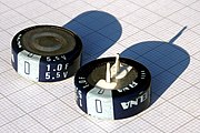
Typical 5 V "button" capacitors that can be fitted on printed circuit boards for data retention with two serial cells in one housing

Radial designs ( lithium-ion capacitors ) for circuit board assembly


Materials of supercapacitors
The properties of supercapacitors are determined by the interaction of the materials used. The combination of electrode material and the type of electrolyte determines the functionality as well as the thermal and electrical properties of the capacitors. In addition, the distinction between the three families of supercapacitors is determined by the type of electrodes used.
Electrodes
Electrodes for supercapacitors must be electrically conductive and have good electrical and mechanical contact with the collector. In general, in order to achieve the largest possible capacity, they should have the largest possible surface area with the smallest possible volume or weight, because the electrode surface primarily determines the size of the capacity value. In addition, the electrodes should be chemically inert with respect to the electrolyte and corrosion-resistant , and should have a high temperature stability. Further required properties for electrodes are environmental compatibility and low price.
Electrodes of this type are typically made of specially treated carbons in its various forms such as e.g. B. activated carbon produced. This porous material has a sponge-like structure, the inner surface of which adds up to a large total surface. Electrodes for a high pseudocapacitance consist of specially suitable materials such as transition metal oxides or conductive polymers. “Customized” pore sizes in the electrode material also lead to pseudocapacitive reactions.
The pore size of electrodes also determines the current carrying capacity of the supercapacitors. Very small pores result in a higher internal resistance with a lower current carrying capacity, but lead to a higher capacitance value. Larger pores guarantee a lower internal resistance and thus a higher current carrying capacity, but result in a lower capacitance value.
Electrodes with large double layer capacitance
Carbon electrodes have a very high static double-layer capacitance. The proportion of pseudocapacitance on such electrodes is usually very low. The Faraday charge exchange only takes place in the angular structure areas or in randomly existing nanopores of the appropriate size. However, in the case of new carbon materials with tailor-made pore sizes, the proportion of pseudocapacitance can increase sharply, so that a clear assignment to a double-layer or pseudocapacitance can no longer be given.
The most commonly used electrode material for supercapacitors is carbon in its various forms, such as activated carbon (AC), activated carbon fiber (AFC), carbide-derived carbon (CDC), carbon airgel, graphite ( graphene ) and carbon nanotubes (CNTs).
Activated carbon

The electrode material in the first double-layer capacitors consisted of industrially produced activated carbon ( english activated carbon (AC) ). Activated carbon has an electrical conductivity of 1,250 to 3,000 S / m along the crystal planes of carbon , which is only about 0.003% of a metallic conductivity, but this is good enough for use as the electrode material of supercapacitors.
Activated carbon forms an extremely porous, open-pored electrode with a sponge-like structure, which, in relation to the volume, has an extremely large specific surface of around 1000 to 3000 m² per gram. That is roughly the area of 4 to 12 tennis courts or, to put it another way, 2.5 g of activated carbon has a surface area roughly the size of a football field. The thickness of the electrode is often only a few 100 µm. An electrode made of activated carbon with a surface area of about 1000 m 2 / g gives a typical double-layer capacitance of about 10 μF / cm² or a specific capacitance of 100 F / g.
Activated charcoal is very inexpensive to produce, is non-toxic, chemically inert and corrosion-resistant . It does not contain any environmentally damaging substances and can also be made from inexpensive natural raw materials. As of 2010, practically all commercial supercapacitors use activated carbon in powder form, which is environmentally friendly made from coconut shells.
The disadvantage of electrodes made of activated carbon is that, in contrast to electrodes made of nanotubes, only less than 1/3 of the area is available for the formation of a double-layer capacitance. Higher surface utilization with other carbon materials is possible, but these are associated with higher costs.
Electrodes made from activated carbon mainly have a static double-layer capacitance. However, special carbons with pore diameters in the range of <2 nm are only accessible to de-solvated ions and are therefore also effective in a pseudocapacitive manner.
Activated carbon fiber

Activated carbon can be carbon fibers ( English activated carbon fiber (AFC) ) are processed, which have micron a typical diameter of about 10 degrees. The fibers can be spun into a fabric for flexible electrodes. A special tissue can be produced in a controlled manner with micropores with a diameter of <2 nm. With such a tissue electrode surfaces of about 2500 m 2 / g result. The advantages of electrodes made of activated carbon fiber fabric are, in addition to the high specific capacitance, good conductivity along the fiber axis and good electrical contact with the collector.
The disadvantage of the small pore size is the increase in the line resistance in the electrolyte, which reduces the power density .
AFC electrodes predominantly have a high double-layer capacitance, but due to the tailor-made pore size they can also have a significant proportion of pseudocapacitance.
Carbon airgel
Carbon - airgel is a synthetic , very highly porous and ultra lightweight material of an organic gel , in which the liquid component of the gel by pyrolysis with a gas was replaced. Aerogels are also known as “frozen smoke”.
Carbon airgel electrodes are made with the pyrolysis of resorcinol - formaldehyde .
Carbon airgel has better electrical conductivity than activated carbon. It enables thin and mechanically stable electrodes with a height in the range of several hundred micrometers with a uniform pore size. Due to its high mechanical stability, carbon airgel can be used as an electrode material for supercapacitors with high vibration resistance.
In research laboratories, electrodes made of carbon aerogels have been developed which have a large surface area of 400 to 1200 m 2 / g with a specific capacity of 104 F / cm 3. These electrodes have both a very high energy density of 90 Wh / kg and a high power density of 20 W / g.
In 2013 a graphene airgel with a density of only 0.16 mg / cm³ was developed.
Airgel electrodes for supercapacitors can also be coated or doped, so they are to be assigned to the area of composite electrodes.
Carbide-derived carbons

Carbide -derived carbons ( English carbide-derived carbon (CDC) ), also called "tunable nanoporous carbon" ( English tunable nanoporous carbons ) called, consist of a number of substances selected from carbides such. B. silicon carbide and titanium carbide have been converted into pure carbon by thermal decomposition or chemical halogenation .
Electrodes made from CDC have large surfaces with customized pore sizes. They can be produced with pore sizes ranging from micropores to mesopores. Pores with pore diameters of <2 nm significantly increase the pseudocapacity of the electrode, because de-solvated ions that can penetrate the small pores of the CDC electrode are much smaller than ions with their solvation shell, which increases the packing density of the intercalated ions, which generate the pseudocapacitance through Faraday charge exchange. These CDC electrodes have a 75% higher energy density than conventional electrodes made of activated carbon.
In 2013, these electrodes were used in supercapacitors with the capacity of 4,000 F and an energy density of 8.3 Wh / kg. They achieved a cycle stability of 1 million charge-discharge cycles.
Graph

Graphene consists of a two-dimensional hexagonal (honeycomb-shaped) lattice of carbon atoms. Several layers of graphene on top of each other result in graphite. Graphene can be produced as an ultra-thin layer similar to paper .
Graphene has a high conductivity of> 1700 S / m and has a very large gravimetric surface of 2630 m 2 / g, with which supercapacitors with a capacity of 550 F / g can theoretically be produced.
A development in 2012 uses the good conductivity of the flat graphene layer directly as an electrode without a collector of an extremely flat supercapacitor for portable applications.
Graphite layers can be bent and packed so crumpled that mesopores are formed between the layers and they do not lie flat on top of each other, like graphite. The pores are relatively large and therefore easily accessible to the charge carriers, which enables very fast loading / unloading. This would enable supercapacitors with graphene electrodes to be built for 100/120 Hz filter applications, an application that was previously not achievable for supercapacitors.
In a development, supercapacitors with graphene electrodes achieved the very high specific energy density of 85.6 Wh / kg at room temperature.
Graphene can be produced as a laboratory sample in various laboratories in 2013, but is not yet available in large quantities.
Carbon nanotubes

Carbon nanotubes ( English carbon nanotubes (CNT) ) are shaped into cylindrical nanotubes graphene layers. There are single walled nanotubes ( English single wall nanotubes (SWNT) ) and multi-walled nanotubes ( English carbon nanotubes (CNT) ) in which a plurality of single-walled nanotubes are arranged coaxially nested. The diameter of the SWNTs can vary and are in the range from micropores to mesopores with values between 1 and 3 nm. The nanotubes can grow directly on a substrate that can serve as a collector, e.g. B. on a silicon wafer, whereby the good electrical conductivity of the carbon in the axial direction leads to an increase in the power density.
Compared with the theoretically maximum electrode surface area of activated carbon (3000 m 2 / g), CNT electrodes only have a moderate surface area of around 1315 m 2 / g. Because of the better wettability, CNT electrodes still have a higher capacity than activated carbon electrodes, e.g. B. 102 F / g for MWNT and 180 F / g for SWNT electrodes. It is expected that supercapacitors with CNT electrodes will achieve an energy density of 21 Wh / kg at the nominal voltage of 2.7 V.
Similar to CDC electrodes, the pore size of mats made of single-walled or multi-walled nanotubes can be precisely adapted to the ion diameter from the electrolyte in order to increase the proportion of pseudocapacitance. However, the repeated intercalation during the charging and discharging processes causes a change in volume that reduces the mechanical stability of the pores, so that the cycle stability of supercapacitors with CNT electrodes is still limited. Research is in progress to improve this behavior.
Electrodes with carbon nanotubes are well suited for particularly flat designs; the typical mechanical height of a nanotube electrode is approx. 20 to 100 µm.
In 2013, the production of SWNTs was significantly more cost-intensive than that of MWNTs. There was also no mass production of supercapacitors with CNT electrodes at that time.
Large pseudocapacitance electrodes
Electrodes made from oxides of transition metals or from conductive polymers have the property of being able to produce not only a double-layer capacitance but also more redox reactions combined with Faraday charge exchange. They are the prerequisite for pseudocapacitors, that is, supercapacitors with predominantly pseudocapacitance.
Transition metal oxides
The transition metal oxides , which, as electrodes, can produce a high pseudocapacitance, are best researched and understood by the studies of BE Conway . Many transition metal oxides are able to perform redox reactions with Faraday charge transfer. These include the oxides of ruthenium (RuO 2 ), iridium (chem | IrO 2 ), iron (Fe 3 O 4 ), manganese (MnO 2 ). But also sulfur compounds such. B. Titanium sulfides (TiS 2 ) or their combinations are able to form pseudocapacities.
Ruthenium (IV) oxide in combination with sulfuric acid H 2 SO 4 as the electrolyte provides one of the best examples of pseudocapacity. This combination has an approximately 10-fold higher specific capacity of 720 F / g, an approximately 5-fold higher gravimetric energy density of 26.7 Wh / kg compared to electrodes made of activated carbon.
Further advantages of these electrodes are the good electrical conductivity and the high cycle stability of more than one million cycles. Because of the high price, such pseudocapacitors are only manufactured for military applications.
Electrodes made of less expensive oxides have been widely investigated, the most common being electrodes made of manganese dioxide (MnO 2 ). So far (2013), however, none of these examined electrodes has been used commercially in supercapacitors.
Conductive polymers
Another electrode material with a high pseudocapacitance are conductive polymers such as polypyrrole , polyaniline , pentacene or polythiophene . These electrodes are inexpensive and, due to the additional pseudocapacitance, lead to the significantly higher specific capacitance of around 450 F / g.
The electrodes made with conductive polymer are sensitive to overvoltages. If the voltages are too high, these materials oxidize and are thus permanently destroyed.
In addition, due to chemical instabilities in their electrochemical reactions, pseudocapacitors have a reduced cycle stability of about 10 4 to 10 5 cycles compared to double-layer capacitors of about 10 6 cycles. However, they are still significantly more cycle-stable than accumulators.
Electrodes for hybrid capacitors
All hybrid supercapacitors that are successful on the market are designed asymmetrically . They combine static electrical energy storage in a double-layer capacitance with Faraday energy storage through charge exchange by coupling a double-layer electrode with an electrode with a high pseudocapacitance. In hybrid capacitors, the electrode for the pseudocapacitance gives a high energy density, while the double-layer electrode gives a high power density.
The asymmetrical structure of hybrid capacitors combines two electrodes with different capacities. Therefore the total capacitance of the capacitor is distributed according to the respective individual capacitance of its electrodes according to the formula of the series connection of two capacitors, see # Capacitance distribution . This means that the capacitance of the asymmetrical hybrid capacitor can be doubled compared to a symmetrical double-layer capacitor.
Although the pseudocapacitive electrodes generally have a higher capacitance and lower internal resistance, their dielectric strength and, above all, in the case of electrodes made of conductive polymers, their cycle stability is lower than that of double-layer electrodes. The asymmetrical structure of the hybrid capacitors alleviates these disadvantages and creates the conditions for higher energy and power density as well as for better cycle stability.
In hybrid capacitors, composite electrodes or electrodes from the field of accumulators are predominantly used, the asymmetrical coupling of a double-layer and a pure pseudo-electrode belongs more to the research area.
Composite electrodes
Composite electrodes consist of the basic material carbon, which is coated with pseudocapacitively active material, or in whose atomic structure pseudocapacitively active material is inserted. This combination gives the electrode both a high double layer capacitance and a high pseudocapacitance. The resulting total capacitance is significantly higher than that of a pure double-layer capacitor.
The proportion of pseudocapacitance in composite electrodes can be increased by tailor-made pore sizes and the associated intercalation of desolvated ions. New developments with carbon nanotubes are particularly promising. CNTs with polypyrrole inclusions or coatings achieve very good wettability with the electrolyte and a uniform three-dimensional distribution of the electrical charge. In addition, the structure of coated carbon nanotubes has shown that the mechanical stresses caused by the Faraday charging and discharging processes are lower than with pure redox-active polymer electrodes, which results in greater cycle stability.
However, composite electrodes can also be doped with a pseudocapacitive active material . This is done in the development of CNT composite electrodes that use, for example, transition metal oxides such as RuO 2 , IrO 2 , MnO 2 or nitrides of molybdenum , titanium and iron as pseudocapacitive active material. Such composite electrodes achieve specific capacitance values in the range from 150 to 250 μF / cm².
Hybrid capacitors with composite electrodes doped with lithium ions are already on the market . In these electrodes, the relatively small lithium atoms are "embedded" in the carbon between the levels, creating an intercalation compound (e.g. LixnC ). which leads to a large pseudocapacitance. With this doping, a bias voltage of the electrode is generated in these lithium-ion capacitors , which increases the nominal voltage of the capacitor to 3.8 to 4 V. The higher voltage causes the significantly higher energy density of the Li-ion capacitors compared to standard supercapacitors.
Battery electrodes
The development of electrodes for new types of accumulators, here called “battery electrodes” due to a colloquial generalization, has a major influence on the electrodes of supercapacitors.
The development of the lithium-ion battery with carbon electrodes in 1985 by Akira Yoshino, for example, meant that electrodes were also developed in the field of supercapacitors that were doped with lithium ions. This then resulted in the lithium-ion capacitors . The former battery electrodes became electrodes for supercapacitors, which then fall under the definition of composite electrodes.
electrolyte
The electrolyte in supercapacitors, the electrically conductive connection between the two electrodes, determines the voltage window in which the capacitor can be operated, its temperature range, the internal resistance (ESR) and, via its stability, the long-term behavior of the capacitor.
An electrolyte always consists of a solvent with dissolved chemicals that dissociate into positive cations and negative anions , thereby making it conductive. The more ions the electrolyte contains, the better its conductivity. The electrolyte must be able to penetrate the porous, sponge-like or cross-linked structure of the electrodes; its viscosity must be small enough to be able to fully wet the electrode surface. It must also be chemically inert and must not chemically attack the materials of the capacitor. The other requirements for the electrolyte, the desired temperature range and the required dielectric strength come from the area of applications. There is no such thing as an ideal electrolyte; the properties of an electrolyte are always a compromise between performance and requirement profile.
The electrolyte also has an influence on the capacity of an electrode. With the same electrode material made of activated carbon, a capacity of 160 F / g is achieved, for example, with a water-containing electrolyte. With an electrolyte based on an organic solvent, however, only a capacity of 100 F / g is achieved.
Water is a relatively good solvent for inorganic chemicals . With acids such as sulfuric acid (H 2 SO 4 ), alkalis such as potassium hydroxide (KOH) or salts such as quaternary phosphonium salts , sodium perchlorate (NaClO 4 ), lithium perchlorate (LiClO 4 ) or lithium hexafluoridoarsenate (LiAsF 6 ), relatively high conductivity values of around 100 up to 1000 m S / cm can be achieved. Inexpensive water-containing electrolytes, however, have low dielectric strengths of approx. 0.5 V per electrode (approx. 1.0 V per capacitor) and are limited in their operating temperature range, especially at low temperatures. More recent results show that operating voltages of up to 1.6 V are possible with neutral aqueous electrolytes. Water-containing electrolyte systems are mainly used in supercapacitors with low energy density but high power density .
Electrolytes with organic solvents such as acetonitrile , propylene carbonate , tetrahydrofuran , diethyl carbonate , γ-butyrolactone and solutions with quaternary ammonium salts or alkylammonium salts such as. B. Tetraethylammonium tetrafluoroborate (N (Et) 4 BF 4 ) or triethyl (methyl) ammonium tetrafluoroborate (NMe (Et) 3 BF 4 ) are more expensive than aqueous electrolytes, but have a higher dielectric strength of typically 1.35 V per electrode (2.7 V per capacitor) and a higher temperature range. Their conductivity of around 10 to 60 mS / cm leads to a lower power density, but since the energy density increases with the square of the voltage, supercapacitors with organic solvent electrolytes have a slightly higher energy density than EDLCs with aqueous electrolytes.
Various alternative electrolytes are being researched that allow a larger voltage window in order to increase the energy density of the entire supercapacitor. Ionic liquids , super-concentrated electrolytes and conductive polymers are the most important starting points for research.
Separators
Separators should mechanically separate the two electrodes from one another in order to prevent a short circuit. They can be very thin (a few hundredths of a millimeter) and have to be very porous in order to contribute as little as possible to the internal resistance (ESR) of the capacitor. In addition, they have to be chemically inert in order to keep the influence on the long-term stability and conductivity of the electrolyte low. Inexpensive solutions use open capacitor papers as separators, professional supercapacitors use porous plastic films, glass fiber fabrics or porous ceramic fabrics as separators.
Collectors and housings
The collectors (current collectors) are used to make electrical contact with the electrode material and connect them to the terminals of the capacitor. They must have good conductivity, after all peak currents of up to 100 A should be distributed to the capacitor cell or taken from it without any problems. If the housing is made of metal as usual, the collectors and housing should be made of the same material, usually aluminum, because otherwise a galvanic cell would form in the presence of an electrolyte, which could lead to corrosion . The collectors are either sprayed onto the electrodes using a spray method or consist of a metal foil on which the electrode is attached.
Electrical Properties
capacity
The capacitance of supercapacitors results from the series connection of the two capacitances C 1 and C 2 (at the electrodes), see # Capacity distribution .
Influence of the pore structure on the capacity


The mobility of the charge carriers in the electrolyte is limited. In the porous structure of the electrodes, they have to travel different distances. In the first area of the pore they are more quickly at their destination than at the end of a pore. The ions penetrating the pores gradually increase the capacity, while the flowing current has to overcome an ever increasing line resistance. When the capacitor is switched off, the same time curve takes place in the opposite direction.
The capacitive properties that result from this can be described electrically quite well with a series connection of RC elements connected in series . So in order to be able to measure the total capacitance of the capacitor, all individual capacities must be summarized using the serial RC time constants. Thus, the total value of the capacitance of a supercapacitor can only be determined with one measurement that also detects the behavior of the ion charge over time and is therefore very time-consuming. Such a measurement must be standardized in order to compare the measurement results.
Nominal capacitance measurement conditions

The capacity of commercial supercapacitors is in the data sheets as the nominal capacity C N ( English Rated capacitance C R specified). This is the capacitance value for which the capacitor is manufactured. The nominal capacity value is provided with a tolerance, usually 20%, and must lie within this tolerance range. The typical capacitance values of supercapacitors are in the Farad (F) range.
Because of the strongly time-dependent charging behavior, the capacitance of supercapacitors cannot be measured with an alternating voltage, as is the case with conventional capacitors. It is therefore determined from the energy content W of a capacitor charged with the charging voltage U Charge :

For this purpose, the capacitor is first charged to its nominal voltage with a constant current source. Then it is held at this voltage value for 30 minutes and then discharged with a defined discharge current I discharge , whereby the time is determined in which the voltage drops from 80% to 40% of the nominal voltage, see picture on the right.
The value of the discharge current depends on the application for which the supercapacitors are intended. The IEC 62391-1 standard defines four classes here:
- Class 1, preservation of memories, discharge current in mA = 1 C (F)
- Class 2, energy storage, discharge current in mA = 0.4 C (F) U (V)
- Class 3, power applications, discharge current in mA = 4 C (F) U (V)
- Class 4, instantaneous power, discharge current in mA = 40 C (F) U (V)
The capacity C results from the formula:

The capacity determined in this way is also called "DC voltage capacity".
The measurement methods specified by the individual manufacturers largely correspond to those according to IEC standards 62391-1 and -2.
Frequency dependence of the capacitance

The standardized measuring procedure for measuring the capacitance is very time-consuming. In industrial production, supercapacitors cannot be checked using these methods. The specified nominal capacitance is therefore measured with a much faster measuring method with a lower measuring frequency than the alternating voltage capacitance and calculated with the help of a correlation factor. However, the capacity of a supercapacitor is very dependent on frequency. At a measuring frequency of 10 Hz, the measured value drops to only around 20% of the DC voltage value. The correlation factor can therefore only be determined with a great deal of experience and through comparisons.
The strong time dependency of the capacitance, due to the limited charge carrier mobility , has in practice the consequence that in many applications, especially with high peak current loads, the nominal capacitance value of the capacitor of the circuit is not available. In order to calculate the capacitance value required in the application, it has proven to be useful for applications with a high current load to start from the required energy W application and then estimate the voltage drop ΔU across the capacitor in a practical manner, for example as a voltage drop from 0.9 U R to 0.4 U R . Then the required capacity is calculated with:

Dielectric strength

Supercapacitors work with very low operating voltages in the range of just a few volts. Because even small overvoltages can irreparably damage the capacitor, compliance with the voltage specified in the data sheets is of great importance. This voltage is the rated voltage U N ( English Rated voltage U R ). It is the maximum DC voltage or peak value of the pulse voltage that may be continuously applied to the capacitor within the specified temperature range.
The nominal voltage is specified in such a way that it has a safety margin in relation to the chemically caused decomposition voltage of the electrolyte. The decomposition voltage is the voltage at which the molecules of the electrolyte solvent break apart. Water then breaks down into hydrogen and oxygen . Exceeding the decomposition voltage leads to gas formation and can lead to the destruction of the capacitor.
Standard supercapacitors with water-based electrolytes are usually specified with nominal voltage values of 2.1 to 2.3 V, capacitors with solvent electrolytes with nominal voltages of 2.5 to 2.7 V. With some hybrid capacitors such as e.g. B. lithium-ion capacitors with doped anode , a dielectric strength of 3.8 to 4 V is achieved, but due to the doping, a lower voltage limit of about 2.2 V must not be fallen below.
The nominal voltage of supercapacitors is usually lower than the required operating voltage in the application. In order to achieve the required operating voltage, supercapacitors must be connected in series. Since the individual capacitors in their properties, z. B. in the ESR value, they have to be balanced with an active or passive balancing . Passive balancing can be done with resistors, with active balancing an electronic control circuit ensures the even distribution of the capacitor voltages.
Internal resistance

The charging or discharging of a supercapacitor is associated with a polarization of the ions in the electrolyte and a movement of the charge carriers through the separator deep into the pores of the electrodes. This movement of the ions in the electrolyte causes losses that can be measured as the internal resistance of the capacitor. The internal resistance strongly depends on the composition of the electrolyte and is series and manufacturer-specific.
With the electrical model of serially connected RC elements , see capacitance , it can easily be explained that the internal resistance of supercapacitors increases with a time delay as the penetration depth of the charge carriers into the pores of the electrodes increases. Since the charge carrier mobility is limited, not only the capacitance but also the internal resistance is time-dependent and thus also strongly frequency-dependent.
The effective internal resistance of a supercapacitor, the internal resistance R i , sometimes also called ESR DC , is calculated using the voltage drop ΔU 2 , which results from the intersection of the extension of the straight section of the discharge voltage with the discharge curve at the time of the start of discharge, using the following formula:

The discharge current for measuring the internal resistance is the current according to the classification according to IEC 62391-1, see # Capacity . The value determined in this way is a direct current resistance.
The DC resistance must not be confused with the ESR or ESR AC ( English equivalent series resistance, ESR ). The ESR is an alternating current resistance that is measured at 1 kHz, occasionally also at 100 Hz, and can have a significantly lower resistance value. Since the measurement can be carried out much faster with a small alternating current, it serves as a reference in the final measurements after the production of the capacitors, which is converted to the direct current internal resistance with the help of correlation factors.
The internal resistance R i determines several properties of supercapacitors. On the one hand, it limits the charging and discharging speed of the capacitor. Together with the capacitance C of the capacitor, the time constant τ results with

This time constant determines the time limit with which a capacitor can be charged or discharged. A 100 F capacitor with an internal resistance of 30 mΩ has e.g. B. a time constant of 0.03 * 100 = 3 s, i.e. This means that after 3 s charging with a current limited only by the internal resistance, the capacitor has reached 62.3% of the charging voltage. Since it takes about 5 to fully charge the capacitor , the voltage has reached the charging voltage after about 15 s.

The internal resistance R i is also the limiting factor if supercapacitors are used to take advantage of the rapid charging / discharging capability compared to accumulators. Because with the very high charging and discharging currents I that occur in power applications of supercapacitors, internal losses P v occur,

which lead to heating of the capacitor via the internal resistance R i . This warming is the main reason for the size limitation of the charging and discharging currents in the supercapacitors, in particular when charging and discharging processes occur frequently.
Since no reactions that lead to chemical bonds occur with supercapacitors, the internal resistance R i is significantly smaller than that of accumulators.
Energy and power density


The maximum energy W max that can be stored by a super capacitor with the capacity C max and the applied voltage U max is calculated according to the formula:

The energy density is derived from the amount of storable electrical energy. It is either related to the mass of the capacitor and given as gravimetric energy density in Wh / kg or related to volume as volumetric energy density in Wh / cm³ or Wh / l .
The energy densities of supercapacitors have so far (2013) with values of 0.5 ... 15 Wh / kg by far not the values of accumulators. For comparison: A lead accumulator typically stores 30 to 40 Wh / kg and a lithium-ion accumulator around 120… 180 Wh / kg. This means that supercapacitors store only about a tenth of the energy per mass compared to the best accumulators in mass use.
A Ragone diagram is used to visualize the information on the power density and the energy density of components in order to enable a quick comparison of the values with other technologies.
In practice, the maximum energy stored in a capacitor according to the data sheet is not available; it is reduced by the voltage drop across the internal resistance and the remaining energy that remains in the capacitor even after a long discharge. The resulting usable (effective) energy W eff is then calculated as:

Although the energy density of the supercapacitors is lower than that of the rechargeable batteries, the capacitors have an important advantage: their power density is significantly higher. The specification of the power density defines the speed with which the energy can be delivered to a load or absorbed by an energy source.
The power density is determined by the heat generated by the current load via the internal resistance. High power densities enable energy storage applications to buffer loads that briefly require or deliver a high amount of current, for example during regenerative braking or in UPS systems .
The maximum power P max of a capacitor is calculated with the applied voltage U and the internal resistance R i according to the formula:

The power of a supercapacitor is also given either in relation to the mass as gravimetric power density in kW / kg or in relation to the volume as volume power density in kW / cm³ or in kW / l.
The maximum power P max calculated using the above formula applies to power adjustment and reduces the storage efficiency to 50% due to the voltage drop across the internal resistance. The IEC 62391-2 standard therefore suggests adapting the formula for the achievable performance to reality. This results in a formula for an "effective" maximum power for supercapacitors in power applications, in which the internal voltage drop is limited to 20%:

Cycle stability and current load
Because the electrostatic and pseudocapacitive storage of electrical energy in supercapacitors normally takes place without the creation of chemical bonds, the current load on the capacitors, i.e. cyclic charging and discharging currents and also pulse currents, is not limited by slow chemical reactions. The charging and discharging of the capacitor both in the double layer and with the Faraday charge exchange takes place very quickly. The electrical current is only limited by the internal resistance of the capacitor, which is significantly smaller than that of accumulators. As a result, supercapacitors have a much higher current carrying capacity than accumulators.
The current load of supercapacitors with the current I generates an internal heat loss P loss via the internal direct current internal resistance R i

This heat loss heats the capacitor and is passed on to the environment, with a temperature difference remaining in the capacitor compared to the ambient temperature. The resulting capacitor temperature must not exceed the specified maximum value and, in addition to the diffusion rate of gaseous components of the electrolyte from the capacitor housing, is decisive for the service life of the components.
The temperature difference that is permissible compared to the ambient temperature, which arises from the current load, should be a maximum of 5 to 10 K so that it only has a minor influence on the expected service life.
The maximum current carrying capacity specified in data sheets includes charging and discharging current, frequency and pulse duration and applies within the specified temperature and voltage range for a defined service life. The general rule is that a lower current load, which can be achieved either through a lower operating voltage or through slower charging and discharging, as well as the lowest possible ambient temperature, the service life of the capacitor can be extended.
The permissible charging and discharging current specified for continuous load can be significantly exceeded for applications in which a high pulse current is required. In the case of a pulsed current load, the briefly generated heat must then be thermally distributed over longer pauses between the pulses. Such a “peak current” can briefly amount to a maximum current of over 1000 A for large supercapacitors for power applications with a capacity of more than 1000 F according to the data sheet specification. Such currents, however, must not be regarded as permanent values. Because with such high currents, not only does the capacitors heat up strongly, with thermal expansion forming an additional stress factor, but also strong electromagnetic forces that affect the strength of the electrode-collector connection. A high impulse resistance of supercapacitors is not only a question of the temperature load, but also the result of a mechanically robust and stable construction.
Compared to accumulators, however, supercapacitors not only have a much higher current carrying capacity, but they also have a much greater cycle stability. This means that supercapacitors can withstand a much larger number of charge-discharge cycles without chemical processes shortening their service life. The chemical stability, especially in the case of pseudocapacitance with Faraday charge transfer, is already so great in supercapacitors with electrodes made of pseudocapacitive polymers that capacitors made with them can withstand more than 10,000 cycles. That is around ten times what lithium-ion batteries can withstand for power applications. Supercapacitors with a very high proportion of double-layer capacitance and also pseudocapacitors with electrodes made of transition metal oxides achieve a cycle stability of more than a million cycles without the capacitance dropping significantly or the internal resistance increasing significantly.
lifespan

Supercapacitors differ from accumulators not only in their higher current carrying capacity and higher cycle stability, but also in their longer service life . Because the electrostatic and pseudocapacitive storage of electrical energy in supercapacitors normally takes place without the creation of chemical bonds, the service life of these capacitors is mainly determined by the capacitor temperature and the associated diffusion rate of gaseous components of the liquid electrolyte out of the capacitor housing. In addition, the operating voltage also has a certain influence on the service life.
The service life of supercapacitors is determined on a collective in rapid tests at the upper limit temperature and at full nominal voltage. Due to the temperature-dependent slow evaporation of the electrolyte through the seal, electrical parameters change; the capacity falls, the internal resistance increases. Due to these changes in the characteristic values, the capacitors will at some point only be able to fulfill their function to a reduced extent. Therefore, change limits are set, the exceeding of which is assessed as so-called "change failures". If only one of these limits is exceeded or fallen short of in the rapid service life tests, the end of the service life of the capacitor has been reached. The capacitors can still be operated, but with reduced electrical properties.
For the capacity, the limit to change failure according to IEC 62391-2 is reached when the capacity value has decreased by 30% compared to its initial value. According to the standard, the internal resistance is regarded as a change failure if it has exceeded four times the value of its specification.
However, these changes that are permissible according to the standard are usually too high for power applications with high switch-on and switch-off currents. Many manufacturers, whose supercapacitors are intended for high currents, therefore set significantly narrower change limits, for example with only 20% change in capacitance combined with the maximum change in internal resistance to twice the data sheet value. This narrower definition is particularly important for the internal resistance when there is a high current load, since the heat development in the capacitor increases linearly with the internal resistance and with a four times higher internal resistance the heat loss would also be four times higher and this could possibly lead to an impermissible gas pressure development in the capacitor.
The time measured up to the first change failure, rounded, is usually specified by the manufacturers as "life time" ( English life time, load life, endurance ). The notation of this life specification, e.g. B. "5000 h / 65 ° C", includes the time in hours (h) and the upper limit temperature in degrees Celsius (° C). It is heavily dependent on the respective series.
The service life specified in the data sheets at the upper limit temperature can be converted by users into service life times for different operating conditions. With conventional supercapacitors, which are not intended for power applications, this is done in a similar way to aluminum electrolytic capacitors with liquid electrolytes, according to the "10-K law", also known as Arrhenius' law . After that, the estimated service life doubles for every 10 K lower operating temperature because the changes in the electrical parameters are correspondingly slower.

- = service life to be calculated
- = service life specified in the respective data sheet
- = upper limit temperature
- = current operating temperature of the capacitor cell


If a series is specified with 5000 h at 65 ° C as in the adjacent figure, the capacitors will show the same changes in electrical parameters with around 10,000 h at 55 ° C as after 20,000 h at 45 ° C, but with twice as long an operating time the lower temperature.
The service life of supercapacitors also depends on the operating voltage. No generally applicable formula can be given for this voltage dependency of the service life. The course of the curve, which emerges from the adjacent picture, is therefore only to be seen as an empirical value of a manufacturer.
Although the service life can be calculated using the above formula, the result of this calculation is only an estimate of the service life as a statistical mean value of a collective of capacitors used under similar conditions.
Residual current and self-discharge
The static storage of electrical energy in the Helmholtz double layers takes place at a distance between the charge carriers that is in the molecular range. At this small distance, effects can occur that lead to the exchange of charge carriers. This self-discharge can be measured as a residual current, also known as leakage current. This residual current depends on the voltage and the temperature on the capacitor. At room temperature, based on the amount of charge stored, it is so low that the self-discharge of the capacitor is usually specified as a charge loss or as a voltage loss for a certain period of time. An example is a “5 V / 1 F gold capacitor” from Panasonic, whose voltage loss at 20 ° C in 600 hours (25 days) is around 3 V, i.e. 1.5 V for the single cell. The self-discharge rate is thus higher than that of accumulators and, in comparison, restricts the areas of application.
polarity
In the case of supercapacitors with symmetrical electrodes, the polarity arises from the application of voltage during production; in the case of asymmetrical electrodes it is also due to the design. Super capacitors are therefore polarized capacitors. They must not be operated in the "wrong" polarity contrary to the polarity identification. This also excludes operation with alternating voltages. Operation with the wrong polarity leads to gas development and destruction of the capacitor.
As with other polarized capacitors, the polarity of supercapacitors is marked with a minus bar in the insulating cover (-) to identify the cathode.
Technical data in comparison
Technical specifications
In the case of supercapacitors, similar to electrolytic capacitors, the combination of customized electrodes with an electrolyte adapted to the application leads to a large number of different technical solutions with different technical values. Especially with the development of low-resistance electrolyte systems in combination with electrodes with high pseudocapacitance, a wide range of technical solutions is possible. The range of supercapacitors on the market is correspondingly diverse. As can be seen from the following table, the capacitors from the various manufacturers therefore differ significantly in terms of the values for the capacitance range, the cell voltage, the internal resistance and the energy density.
In the table, the internal resistance relates to the largest capacitance value of the respective manufacturer. In a very rough estimate, the supercapacitors can be divided into two groups. The first group with internal resistances greater than approximately 20 mΩ has capacitance values from 0.1 to 470 F. These are the typical "double-layer capacitors" for data retention or similar applications. The second group with capacitance values of around 100 to 12,000 F has significantly lower internal resistances, some of which go down to around 0.2 mΩ. These supercapacitors are suitable for power applications.
This table does not show the percentage of double-layer and pseudo capacitance in the total capacitance of an offered capacitor. The manufacturers themselves are only rarely ready to publish something on this subject. Even these few details, compiled in the article by Pandolfo and Hollenkamp, do not reveal a percentage distribution of the proportion of double-layer and pseudocapacitance.
Characteristic values
| Manufacturer | Capacitor name |
Capacitance area (F) |
Cell voltage (V) |
Volumetric energy density (Wh / dm³) |
Gravimetric energy density (Wh / kg) |
Hints |
|---|---|---|---|---|---|---|
| APowerCap | APowerCap | 4… 550 | 2.7 | - | ≤4.5 | - |
| AVX | BestCap® | 0.05 ... 0.56 | 3.6 | ≤0.13 | - | Modules up to 20 V. |
| Cap-XX | Cap-XX | 0.17 ... 2.4 | 2.5 | ≤2.2 | - | - |
| CDE | Ultracapacitor | 0.1 ... 1.0 | 3.6 | - | - | - |
| cooper | PowerStor | 0.22 ... 3000 | 2.5 / 2.7 | - | - | Modules up to 62 V |
| Elna | DYNACAP POWERCAP |
0.047 ... 1500 |
2.5 / 3.6 | - | - | - |
| Evans | Capattery | 0.001 ... 10 | 5.5 ... 125 | - | - | Hybrid capacitors |
| Green tech | Super capacitor | 2… 600 | 2.7 / 2.8 | - | - | Modules up to 64 V |
| HCC | HCAP | 15 ... 3500 | 2.7 | ≤8.1 | ≤6.8 | - |
| Illinois | Supercapacitor | 0.3 ... 800 | 2.3 / 2.7 | ≤8.6 | ≤6.6 | - |
| Ioxus | Ultracapacitor | 100 ... 3000 | 2.7 | ≤8.7 | ≤6.4 | Modules up to 130 V. |
| JSR Micro | Ultimo | 1100 ... 3300 | 3.8 | ≤20 | ≤12 | Li-ion capacitors |
| Korchip | STARCAP | 0.02 ... 400 | 2.5 / 2.7 | ≤7.0 | ≤6.1 | - |
| LS Mtron | Ultracapacitor | 100 ... 3400 | 2.7 / 2.8 | - | - | Modules up to 130 V. |
| Maxwell | Boostcap® | 1… 3400 | 2.2 / 2.8 | - | ≤6.0 | Modules up to 160 V |
| Murata | EDLC | 0.22 ... 1.0 | 4.2 / 5.5 | ≤2.7 | ≤3.1 | 2 cells in series |
| NEC Tokin | Supercapacitor | 0.047 ... 200 | 2.7 | - | - | - |
| Nesscap | EDLC, pseudocapacitor |
3… 50 50… 300 |
2.7 2.3 |
≤7.1 ≤12.9 |
≤4.5 ≤8.7 |
Modules up to 125 V. |
| Nichicon | EVerCAP® | 1.0 ... 6000 | 2.5 / 2.7 | - | - | - |
| NCC, ECC | DLCCAP | 350 ... 2300 | 2.5 | - | - | - |
| Panasonic | Gold cap | 0.1 ... 70 | 2.3 / 2.5 | - | - | Modules up to 15 V. |
| Samwha | Green-Cap® ESD-SCAP |
3… 7500 | 2.5 / 2.7 | ≤7.6 | ≤7.0 | - |
| Six sat | C capacitor | 330 ... 3200 | 3.0 | - | <8.0 | Modules up to 144 V and storage systems up to 12 MW |
| skeleton | SkelCap | 250 ... 4500 | 2.85 | ≤14.1 | ≤10.1 | Modules up to 350 V |
| Taiyo Yuden | PAS Capacitor LIC Capacitor |
0.5 ... 20 0.5 ... 270 |
2.5 / 3.0 3.8 |
- - |
- - |
Pseudocapacitors Li-ion capacitors |
| VinaTech | Hy-cap | 1.0 ... 500 | 2.3 / 3.0 | ≤8.7 | ≤6.3 | - |
| Vishay | ENYCAP | 4… 90 | 1.4 / 2.8 | - | ≤3.6 | Modules up to 8.4 V. |
| WIMA | SuperCap | 100 ... 3000 | 2.5 | - | - | Modules up to 28 V. |
| YEC | Kapton capacitor | 0.5 ... 400 | 2.7 | - | - | - |
| Yunasko | Ultracapacitor | 480… 1700 | 2.7 | - | - | Modules up to 48 V |
Comparison with other technologies
Supercapacitors compete on the one hand with electrolytic capacitors and on the other hand with accumulators, in particular with lithium-ion accumulators . The following table compares the most important technical data of the three different families within the supercapacitors with electrolytic capacitors and batteries.
| Characteristic values | Electrolytic capacitors |
Super capacitors | Lithium- ion accumulators |
||
|---|---|---|---|---|---|
| Super capacitors for data retention |
Super capacitors for power applications |
Hybrid capacitors (Li-ion capacitors) |
|||
| Operating temperature range (° C) | −40 ... + 125 | −20 ... +70 | −20 ... +70 | −20 ... +70 | −20 ... +60 |
| Nominal voltage per cell (V) | 4… 550 | 1.2 ... 3.3 | 2.5 ... 3.3 | 2.2 ... 3.8 | 2.5 ... 4.2 |
| Charge / discharge cycles | unlimited | 10 5 … 10 6 | 10 5 … 10 6 | 2 · 10 4 … 10 5 | 500… 10 4 |
| Capacity range (F) | ≤ 1 | 0.1 ... 470 | 100 ... 12000 | 300 ... 2200 | - |
| Energy density (Wh / kg) | 0.01 ... 0.3 | 1.5 ... 3.9 | 4… 9 | 10 ... 25 | 100 ... 265 |
| Effective power density (kW / kg) | > 100 | 2… 10 | 3… 10 | 3… 6 | 0.3 ... 1.5 |
| Self-discharge time at room temperature | short (days) |
medium (weeks) |
medium (weeks) |
medium (weeks) |
long (months) |
| Efficiency (%) | 99 | 95 | 95 | 90 | 90 |
| Lifetime at room temperature (years) | > 20 | 5… 10 | 5… 10 | 5… 10 | 3… 5 |
Electrolytic capacitors have advantages because of their suitability for decoupling low-frequency frequencies up to around 500 kHz and their high dielectric strength up to 550 V. In contrast, their storage capacity is significantly lower.
Like accumulators, supercapacitors are only suitable for pure DC voltage applications. The advantages of supercapacitors over accumulators are the longer service life, the significantly higher power density with high peak current capacity, the significantly greater cycle stability and the maintenance-free operation. The disadvantages are the higher price, the lower energy density and the faster self-discharge.
standardization

The technical properties of supercapacitors differ considerably from one another. Particularly in applications with high peak currents, the electrical values are often dependent on the measurement conditions, so that standardized tests and measurement regulations are essential in order to achieve comparability of the components.
These tests and measurement regulations as well as the requirements for the tested capacitors are set out in an internationally harmonized ( IEC ) standard that has been adopted in the German-speaking area by the respective country organizations ( DIN , OEVE / OENORM , SN ) as the European standard EN . That is the:
- Generic specification IEC 62391-1, electrical double-layer capacitors for use in electronic devices
- Class 1 , data retention from memories,
- Class 2 , energy storage , e.g. B. for the operation of drive motors,
- Class 3 , power applications , higher power requirements for longer operation
- Class 4 , instantaneous power , higher peak currents for short-term operation
For the supercapacitors for class 4 power applications, the special requirements are laid down in an internationally harmonized framework specification:
- Framework specification EN 62391-2 , Electric double layer capacitors for power applications
In addition, the following two standards specify the special requirements for supercapacitors for defined areas of application:
- IEC 62576 , requirements for use in automotive electronics
- IEC 61881-3 , requirements for use in the railway sector
Applications
General uses
Supercapacitors have advantages in applications where a large amount of energy is required for a relatively short time or for a very large number of charge / discharge cycles. Typical examples include currents in the range of milliamps or milliwatts for a few minutes up to currents in the range of several hundred amperes or several hundred kilowatts during brief load peaks.
The time t during which a supercapacitor can deliver a constant current I is calculated with:

wherein the voltage to drop.


If the application needs constant power for a certain period of time , this can be calculated with:


whereby the voltage also drops down to.
Supercapacitors are not suitable for AC voltage applications.
Consumer electronics
Supercapacitors stabilize the power supply in applications with rapidly / strongly fluctuating loads. Examples are: laptops , PDAs , GPS , portable DVD players and smartphones .
They deliver large current peaks in a short time and are therefore used in parallel to accumulators in digital cameras to write the image files.
The fast charging capacity of the super capacitors is used for an emergency LED flashlight flashlight.
For do-it-yourselfers, an electric screwdriver with supercapacitors is available that only runs half as long as a battery model, but is charged in 90 seconds.
Supercapacitors provide the energy for extremely fast charging, mains-independent loudspeakers .
Industrial electronics
Supercapacitors provide the energy for electrical consumers, the function of which must continue to be guaranteed in the event of a brief power failure, for example for data retention in electronic data storage devices ( RAM , SRAM ) in industrial electronics. They can also be found as an additional energy source in intelligent electricity meters (smart meters).
In cooperation with accumulators connected in parallel, supercapacitors buffer with strongly fluctuating loads, e.g. B. in radio and telecommunication devices , the currents of the battery and thus dampen load peaks. This can extend the life of the batteries.
A typical industrial application for supercapacitors are uninterruptible power supplies (UPS) for bridging brief power failures. With them, a significant space saving can be achieved compared to electrolytic capacitors.
Supercapacitors are used as a power source to power electric locomotives in some coal mines in China. The advantage of this drive is the fast charging time of the capacitors compared to batteries. The train is ready to run again in less than 30 minutes. This solution significantly reduces the risk of explosion compared to electrical drives with contact wire.
Tractors at airport terminals with an electric drive powered by supercapacitors are already in use. They offer an inexpensive, quiet and pollution-free alternative to diesel tractors.
Renewable energy

Instead of accumulators, supercapacitors are also used in many wind turbines for the emergency power supply for pitch control . This ensures that even if the connection to the power grid is interrupted, enough energy is available at all times to turn the rotor blades into the flag position ("out of the wind") and thus to be able to safely shut down the turbine. Each rotor blade usually has a separate adjustment mechanism with its own condenser unit, each of which is housed in the rotor hub. The main advantage compared to accumulators is the lower maintenance requirement.
Super capacitors can stabilize the voltage generated by photovoltaic systems. This voltage is subject to fluctuations caused by passing clouds or shadowing. The stabilization reduces the cost of the network operator , the mains voltage and mains frequency stabilized to have.
If the design is adequate, supercapacitors are also suitable for short-term storage of electrical energy during photovoltaic feed into the low-voltage network.
Street lighting
Street lights in the city of Sado ( Niigata Prefecture ) are operated without a mains connection. During the day, supercapacitors are charged via solar cells and supply electricity for LED lights after dark. Because of their better low-temperature properties and the longer service life of over 10 years, supercapacitors were preferred to batteries.
Cable car
In some cable cars, the vehicles have a power supply for lighting, intercoms and also for infotainment systems while they are in motion . Since accumulators for charging during station passages and stays have a charging time that is too long, supercapacitors can be used instead, which are charged via a power rail every time you pass through the station. Gondolas with supercapacitors in the power supply can be found in Zell am See and on the Emirates Air Line , the cable car over the Thames in London .

Medical electronics
Supercapacitors are used in defibrillators , in which they provide the energy required for the life-saving impulses.
Aviation electronics
Diehl Luftfahrt Elektronik GmbH has been using supercapacitors as energy sources for the emergency opening of the doors and the activation of the emergency slides in devices for aircraft including the Airbus 380 since 2005 .
Military electronics
The cold start of diesel engines poses a particular challenge to the provision of short-term current peaks. Supercapacitors with low internal resistances have been used for a long time to start diesel engines in tanks and submarines to support the batteries during cold starts.
Other military applications where super capacitors are used because of their high power density, are phased array antennas , power supplies for pulsed laser , avionics Indicators and instruments, airbag -Zünderschaltungen and GPS - guided weapons missiles and projectiles.
Energy recovery
Supercapacitors are also used in regenerative brakes . Due to their high current carrying capacity and cycle stability, high efficiency and long service life, they are ideally suited for storing electrical energy that is obtained from kinetic energy during braking .
railroad
Supercapacitors are used as a supplement to the accumulators as starter batteries in diesel locomotives with diesel-electric drives and to preheat the catalytic converter . Due to their high current-carrying capacity, the capacitors also absorb the energy that is generated when the train is dynamically braking, and they also supply the peak current that occurs when the train starts. In a study it was found that 25 to 30% energy savings are possible. Since the accumulators can be designed correspondingly smaller due to the reduced peak load, the reduction in mass and installation space with this solution enables a higher fuel supply in the locomotives. Maintenance-free and environmentally friendly materials were further decisive advantages for the use of supercapacitors in the decision to carry out this test.
Cranes and forklifts
Mobile hybrid diesel-electric container cranes move and stack containers within a container terminal . Lifting the containers requires a large amount of energy. Some of the energy is recovered in the container terminal in Kuantan (Malaysia) with the help of supercapacitors while the load is being lowered. This enables considerable energy savings. Another advantage of this design is the miniaturization of the primary diesel engine, since the peak load when lifting the load can be taken over by the energy stored in the capacitors and the electric motors fed by it.
In a special version of a “triple hybrid forklift ”, a fuel cell is used as the primary energy source, which is used to charge a combination of accumulators and supercapacitors connected in parallel. The supercapacitors supply the current for the peak load when the load is lifted and absorb the energy released when the load is lowered. This triple hybrid system offers more than 50% energy savings compared to a pure diesel or fuel cell system.
City and tram vehicles

Supercapacitors can not only temporarily store electrical energy from regenerative braking of light rail and tram cars "on-board", but also offer the possibility of driving short distances without overhead lines. The required energy can be absorbed during the stopping time at the stops via an overhead line installed only here. By eliminating the overhead contact line, considerable savings can be made in setting up the infrastructure. In addition, the visually disruptive overhead lines can be omitted in historical urban areas.
Since 2003, a system from the manufacturer Bombardier Transportation for storing the braking energy recovered during regenerative braking has been tested on a light rail vehicle in Mannheim . This system, called MITRAC Energy Saver , works with super capacitors and is located on the roof of the railcar . It contains several memory blocks made up of 192 individual capacitors, each with 2700 F at 2.7 V, connected in three parallel-connected strings. This results in a 518 V system with an energy content of 1.5 kWh. To accelerate the start-up, this “on-board system” can provide 600 kW for a short time. It can also be used for up to a kilometer without an overhead contact line. With such systems, the peak electricity demand from the grid is reduced by around 50%, and around 30% of the energy required for operation can be saved. Although the equipment with the supercapacitors as energy storage causes additional costs of around 270,000 euros per car, the operator expects that the additional costs will be amortized in 15 years. The test was successfully completed in March 2008 and the test vehicle was dismantled to its normal version. As a result, between 2009 and 2013, Rhein-Neckar-Verkehr put a total of 30 new Rhein-Neckar-Variobahn trains into service with this system for the Mannheim and Heidelberg locations.
The Spanish manufacturer Construcciones y Auxiliar de Ferrocarriles (CAF) offers the “ Acumulador de Carga Rápida ” (ACR) system for its Urbos 3 trams . It has been in use in Seville since 2011 .

In Paris from May 2009 to September 2010 a train on tram line 3 ran with an energy recovery system called "STEEM" from the manufacturer Alstom . It was to be shown that trams can run with the energy stored in the supercapacitors in sections without overhead lines.
A prototype of a light rail vehicle with supercapacitors with a total mass of one ton has been used in Geneva since 2012 to recover braking energy. The storage system was developed by ABB and can store the electrical equivalent of the kinetic energy of the empty train traveling at 55 km / h.
In August 2012, the CSR Zhouzhou Electric Locomotive corporation of China presented a prototype of a light rail vehicle with a sidecar, which is equipped with an energy recovery system. The capacity of the supercapacitors is designed so that the train runs without overhead lines and the capacitor at the stations absorbs the additional energy required for travel.
The recovery of the braking energy can also take place via the overhead line network in stationary storage blocks if the network is not capable of receiving it. To this end, for example, Hong Kong's South Island Metro Line was equipped with two storage units that are equipped with supercapacitors, each of which can take up 2 MW each. The company expects energy savings of around 10% as a result.
City buses

As early as 2001, the so-called “Ultracapbus” was presented to the public by MAN , the first hybrid bus in Europe that was able to recover its braking energy. It was tested in real line operation in Nuremberg in 2001/2002 . Each bus contained eight supercapacitor modules that operated at 640V. The energy content of the modules was 0.4 kWh with a mass of 400 kg and delivered a maximum current of 400 A. The advantages of the system were a significant reduction in fuel consumption (currently 10 to 15% compared to conventional diesel vehicles ), a reduction in CO 2 emissions, leaving the stop without disturbing noise and exhaust emissions , increasing driving comfort (smooth, low-vibration driving) and a reduction in maintenance costs.
Another operational test with supercapacitors for energy recovery was successfully carried out in 2002 with the TOHYCO Rider minibus fleet in Lucerne , Switzerland. The buses can be inductively charged without contact in a few minutes at any stop. All attempts were successful, so that the fleet test was continued in 2004.

In the spring of 2005, an electric bus called “Capabus” was put into trial operation in Shanghai. It is equipped with super capacitors for recuperation and driving. They are charged at the stops with the help of the overhead line that is only installed there for driving operations. In 2013, three such lines with a total of 17 buses were already in operation in Shanghai. The operators assume that the operation will be more cost-effective than with Li-ion batteries because of the higher cycle stability and the longer service life of the capacitors and that it will generate savings of more than 200,000 US dollars compared to diesel operation over its operating life.
Another concept of an electric bus that works completely without overhead lines was presented by the University of Glamorgan ( Wales ). Both hydrogen in combination with a fuel cell and electricity from solar cells are used as an energy source. The intermediate storage takes place via batteries and super capacitors connected in parallel. This “tribrid” bus is used to transport students around the campus.
Motorsport

The FIA , the international governing body of motor sport has, in 2007, allowed one race car Formula in the rules for that in the drive train of the super capacitors and batteries in parallel may only be used a 200 kW hybrid drive contains.
By feeding in the braking energy and delivering it back when accelerating, this "Kinetic Energy Recovery System" ( KERS ) saves around 20% fuel.
Under the rules for prototypes of the 24-hour race at Le Mans , Toyota developed a racing car, the Toyota TS030 Hybrid LMP1, which has a hybrid drive train and uses an energy storage device equipped with supercapacitors to recover the braking energy.
In the 2012 race, this sports prototype drove its fastest lap just 1.055 seconds slower (3: 24,842 compared to 3: 23,787) than the fastest car, an Audi R18 e-tron quattro with flywheel storage. These two vehicles, which recovered braking energy in different ways, were the fastest cars in the race.
Motor vehicles
As far as is known, the electric cars and hybrid vehicles (HEV) delivered to date do not contain any supercapacitors, either in the drive train or in the recuperation (see list of hybrid cars in series production ), although the capacitor industry has made great efforts to clearly highlight the advantages of the capacitors. The braking energy is currently (2014) stored with the help of high-performance batteries in the Toyota Prius in the HSD drive train , which were designed for high cycle stability. The difference in the recovered recuperation energy between the battery solution and a solution with supercapacitors of approximately 10% does not justify the use of supercapacitors, as the actual objective of these vehicles is longer driving performance.
However, all of the major manufacturers have equipped corresponding developments and test setups with supercapacitors or have prototypes that have been presented for years. However, due to the different voltage behavior of the capacitor and battery, the battery management system with DC voltage converter and control electronics designed for the different voltage curves are significantly more difficult, which is synonymous with more weight and higher price.

However, at the end of 2012, the manufacturer Mazda presented a regenerative braking system for the Mazda 2 Demio with a supercapacitor for energy storage, in which the advantages of the supercapacitors such as very high peak current carrying capacity and very high cycle stability combined with long service life and good low-temperature properties as well as great reliability come into their own. In this system, called i-ELOOP , supercapacitors from the manufacturer NCC, which were specially designed for use in vehicles to be more temperature and vibration -proof , are used as storage units in parallel with Li-ion batteries. Mazda expects energy savings of around 10% with this system.
Another hybrid vehicle model series with supercapacitors for braking energy recovery were the Russian yo-cars of the ё-mobil series. In 2010, the entrepreneur Michail Prokhorov presented prototypes of the ë-Concept and ë-Crossover, which use a gasoline-powered rotary piston engine with a generator in continuous operation to supply two electric motors. A supercapacitor briefly provides the motor with higher energy when it accelerates and is charged again when it brakes. The project sponsored by the Russian government was discontinued in 2014 because the market opportunities were assessed as unfavorable.
New developments
Commercially available supercapacitors for professional applications were available in 2013 with an energy density of around 6 Wh / kg, and lithium-ion capacitors with around 15 Wh / kg. With these values, supercapacitors have a significantly lower energy storage capacity than modern accumulators. In order to be able to reach the emerging mass market for electric and hybrid vehicles in particular, a large number of research and development departments in many companies and universities are in the process of developing advances in these special capacitors. The objectives of the research projects are to increase the specific capacity through the development of new nanostructured electrodes, tailor-made pore structures to increase the pseudocapacitance, reduce the internal resistance and thus increase the power density, increase the voltage and temperature resistance, improve the chemical stability of the electrodes and reduce costs through automation in production and cheaper base materials.
Here are some new developments announced in recent years:
| Title of the new development |
date | Energy density (footnote) |
Power density | Cycles | Specific capacity | Hints |
|---|---|---|---|---|---|---|
| Graphene electrodes in subnanometer configuration with high ion density | 2013 | 60 Wh / l | Porous, densely packed graphene electrodes with a large surface area that use capillary forces to produce a high ion density | |||
| Electrode with vertically arranged carbon nanotubes | 2007 2009 2013 |
13.50 Wh / kg | 37.12 W / g | 300,000 | First use see: | |
| Electrode made from “crumpled” one-dimensional graphene layers | 2010 | 85.6 Wh / kg | 550 F / g | The electrodes with two-dimensional structure form mesopores with large pseudocapacitance. | ||
| Customized three-dimensional crystalline graphite electrode | 2011 | 85 Wh / kg | > 10,000 | 550 F / g | Chemically activated graphite with a three-dimensional crystalline electrode structure with meso / macropores | |
| Activated graphene-based carbon with macro and mesopores | 2013 | 74 Wh / kg | Three-dimensional pore structure in graphene-derived carbon with mesopores that are integrated in macropores and have a surface area of 3,290 m 2 / g | |||
| Three-dimensional porous graphene electrode | 2013 | 98 Wh / kg | 231 F / g | Three-dimensional graphene-based electrode material made of single-layer folded graphene sheets with covalent bonds | ||
| SWNT composite electrode | 2011 | 990 kW / kg | Composite electrode with single-walled carbon nanotubes with a tailor-made pore structure in the range of meso- and macropores | |||
| Conjugated microporous electrode made of conductive polymer | 2011 | 53 Wh / kg | 10,000 | The "Aza-Fused π-Conjugated Microporous Framework" is a microporous polymer (CMP) in which some electrons can move freely in its double bonds as an "electron cloud" and is suitable for a large pseudocapacitance. | ||
| Nickel hydroxide composite electrode | 2012 | 50.6 Wh / kg | 3,300 F / g | Asymmetrical composite electrode on which nickel hydroxide is embedded as nanoflakes on carbon nanotubes, coupled with a carbon electrode for a hybrid capacitor with 1.8 V cell voltage | ||
| Battery electrodes nano hybrid capacitor | 2012 | 40 Wh / l | 7.5 kW / l | 10,000 | Li 4 Ti 5 O 12 (LTO) embedded in carbon nanofibers (CNF) coupled with an electrode made of activated carbon | |
| Carbon-airgel composite electrode with embedded nickel - cobaltite | 2012 | 53 Wh / kg | 2.25 kW / kg | 1,700 F / g | Inexpensive and environmentally friendly nickel-cobaltite (NiCo 2 O 4 ) nanocrystals embedded in a carbon airgel electrode result in a high pseudocapacity. | |
| Manganese dioxide composite electrode with intercalated sodium | 2013 | 110 Wh / kg | 1,000 F / g | Electrochemically intercalated sodium ions (Na + ) in a manganese dioxide electrode MnO 2 for fast ion transport with high pseudocapacity. | ||
| Graphene-based planar micro-supercapacitors for “on-chip” energy storage | 2013 | 2.42 Wh / l | Integration of super capacitor structures to decouple interference frequencies. | |||
| Quantum Effect Supercapacitors |
2013 | 480 Wh / kg | Quantum supercapacitors have very small clusters (nanoclusters) of dipolar metal oxides in the rutile structure in their electrodes . Energy is stored by loading the clusters with electrons. The tunnel effect is used here. |
Research into new electrode materials requires measurement methods that show the properties of just one electrode. By using a counter electrode that does not influence the measurements on the test electrode, the characteristics of a newly developed electrode can be recorded. The energy and power density of a complete supercapacitor with the newly developed electrode is usually only about 1/3 of the value measured for the electrode.
market
The market volume for supercapacitors in 2016 was about 240 million US dollars.
Compared to the market for batteries of $ 36.3 billion in 2009, accumulators of $ 11.2 billion (estimated by Frost & Sullivan ), and for capacitors of about $ 18 billion in 2008, the market is supercapacitors are still a niche market. However, this source predicts significant growth and estimates the market at $ 2 billion in 2026.
On the other hand, the market for supercapacitors is predicted to grow to around 3.5 billion US dollars in 2020, in the event that the capacitors are used in particular for the recuperation of braking energy in private cars, but also for other areas of "green" Energy saving can be used.
The prices for supercapacitors are falling. While a typical price of $ 10,000 per kWh was mentioned in 2010, the price for supercapacitors per kWh is estimated by the cleantech online magazine CleanTechnica at $ 2,400 to $ 6,000 in 2016, and at $ 500 for lithium-ion hybrid supercapacitors up to $ 1000.
The market price for 3,000-F supercapacitors dropped from $ 5,000 in 2000 to $ 50 in 2011.
literature
- Héctor D. Abruña , Yasuyuki Kiya, Jay C. Henderson: Batteries and electrochemical capacitors . In: Physics Today . No. 12 , 2008, p. 43–47 ( online [PDF]).
- F. Béguin, E. Raymundo-Piñero, E. Frackowiak: Carbons for Electrochemical Energy Storage and Conversion Systems. Chapter 8: Electrical Double-Layer Capacitors and Pseudocapacitors. CRC Press, 2009, ISBN 978-1-4200-5307-4 , pp. 329-375. (eBook, ISBN 978-1-4200-5540-5 , doi: 10.1201 / 9781420055405-c8 )
- J. O'M. Bockris, MAV Devanathan, K. Muller: On the Structure of Charged Interfaces . In: Proceedings of the Royal Society . tape 274 , no. 1356 , 1963, pp. 55-79 , doi : 10.1098 / rspa.1963.0114 .
- BE Conway: Electrochemical Supercapacitors: Scientific Fundamentals and Technological Applications . Springer, Berlin 1999, ISBN 0-306-45736-9 ( limited preview in the Google book search).
- Farzad Ebrahimi (Ed.): Nanocomposites - New Trends and Developments . InTech, 2012, ISBN 978-953-510-762-0 , doi : 10.5772 / 3389 (open access book).
- Kim Kinoshita: Carbon: Electrochemical and Physicochemical Properties . 1 ed. Wiley-Interscience, New York 1988, ISBN 0-471-84802-6 .
- KW Leitner, M. Winter, JO Besenhard: Composite supercapacitor electrodes . In: Journal of Solid State Electrochemistry . tape 8 , no. 1 , August 5, 2003, ISSN 1433-0768 , p. 15-16 , doi : 10.1007 / s10008-003-0412-x .
- Dagmar Oertel: Energy Storage - Status and Perspectives . In: TAB work report . No. 123 , 2008, p. 86–92 ( PDF section: Electrochemical capacitors).
- Volkmar M. Schmidt: Electrochemical process engineering. Basics, reaction technology, process optimization . Wiley-VCH, Weinheim 2003, ISBN 3-527-29958-0 , pp. 539–639 ( limited preview in Google Book Search - Chapter 7: Electrochemical Energy Technology ).
- Yu M. Vol'fkovich, TM Serdyuk: Electrochemical Capacitors . In: Russian Journal of Electrochemistry . tape 38 , no. 9 , September 1, 2002, ISSN 1023-1935 , p. 935-959 , doi : 10.1023 / A: 1020220425954 .
- Jiujun Zhang, Lei Zhang, Hansan Liu, Andy Sun, Ru-Shi Liu: Electrochemical Technologies for Energy Storage and Conversion . tape 1 . Wiley-VCH, Weinheim 2011, ISBN 978-3-527-32869-7 , pp. 317–376 ( limited preview in Google Book Search - Chapter 8: Electrochemical Supercapacitors ).
Web links
Individual evidence
- ^ A b c d e B. E. Conway: Electrochemical Supercapacitors: Scientific Fundamentals and Technological Applications . Springer, Berlin 1999, ISBN 0-306-45736-9 , pp. 1–8 ( limited preview in Google Book search). See also Brian E. Conway in Electrochemistry Encyclopedia: ELECTROCHEMICAL CAPACITORS Their Nature, Function, and Applications ( April 30, 2012 memento in the Internet Archive ) (accessed December 7, 2015)
- ↑ a b c d e Marin S. Halper, James C. Ellenbogen: Supercapacitors: A Brief Overview. (PDF) In: MITER Nanosystems Group. March 2006, accessed December 7, 2015 .
- ↑ a b c d e Adam Marcus Namisnyk and JG Zhu: A Survey of Electrochemical Super-Capacitor Technology . 2003 ( PDF [accessed December 7, 2015] Bachelor thesis; University of Technology, Sydney; 2003).
- ↑ a b c d Zbigniew Stojek: The Electrical Double Layer and Its Structure . In: Fritz Scholz (Ed.): Electroanalytical Methods: Guide to Experiments and Applications . Springer, Berlin / Heidelberg 2010, ISBN 978-3-642-02914-1 , p. 3–10 ( online [accessed January 5, 2014]).
- ↑ a b B. E. Conway, WG Pell: Double-layer and pseudocapacitance types of electrochemical capacitors and their applications to the development of hybrid devices. In: Journal of Solid State Electrochemistry. 7, 2003, p. 637, doi : 10.1007 / s10008-003-0395-7 .
- ↑ a b Mustapha Jammal: State of the art and application of supercapacitors . GRIN Verlag, 2010, ISBN 978-3-640-52396-2 ( limited preview in Google book search).
- ↑ Elton Capacitor cells ( Memento of the original from June 23, 2013 in the Internet Archive ) Info: The archive link was inserted automatically and has not yet been checked. Please check the original and archive link according to the instructions and then remove this notice. , accessed January 3, 2014
- ↑ Patent US2800616 : Low voltage electrolytic capacitor. Published on July 23, 1957 , inventor: HI Becker.
- ^ J. Ho, TR Jow, S. Boggs: Historical Introduction to Capacitor Technology . (PDF) (accessed January 5, 2014)
- ↑ A brief history of supercapacitors . ( Memento of the original from January 6, 2014 in the Internet Archive ) Info: The archive link was inserted automatically and has not yet been checked. Please check the original and archive link according to the instructions and then remove this notice. (PDF; 1.5 MB) AUTUMN 2007 - Batteries & Energy Storage Technology, accessed on January 5, 2014
- ↑ Patent US3288641 : Electrical energy storage apparatus. Published November 29, 1966 , inventor: RA Rightmire.
- ↑ Patent US3536963 : Electrolytic capacitor having carbon paste electrodes. Published October 27, 1970 , inventor: DL Boos.
- ^ Panasonic, Electric Double Layer Capacitor, Technical guide, 1. Introduction, PDF ( Memento of the original from January 9, 2014 in the Internet Archive ) Info: The archive link was inserted automatically and has not yet been checked. Please check the original and archive link according to the instructions and then remove this notice.
- ↑ DynaCap , ELNA CO., LTD, accessed May 16, 2013
- ↑ a b c Joel Schindall: The Charge of the Ultra - Capacitors . ieee spectrum, page 2, November 2007, accessed January 5, 2014
- ^ BE Conway: Transition from 'Supercapacitor' to 'Battery' Behavior in Electrochemical Energy Storage . In: Journal of The Electrochemical Society . tape 138 , no. 6 , May 1991, pp. 1539–1548 , doi : 10.1149 / 1.2085829 ( PDF ).
- ↑ Patent US5369547 : Energy Density Electrolytic-Electrochemical Hybrid Capacitor. Published November 29, 1994 , inventor: Evans.
- ^ David A. Evans (Evans Company): High Energy Density Electrolytic-Electrochemical Hybrid Capacitor . In Proceedings of the 14th Capacitor & Resistor Technology Symposium , March 22, 1994 ( PDF , accessed January 5, 2014)
- ↑ Capattery® Series Evans Capacitor Company 2007 (accessed January 5, 2014)
- ^ David A. Evans: The Littlest Big Capacitor - an Evans Hybrid. Technical Paper - Evans Capacitor Company 2007, accessed January 5, 2014
- ↑ FDK history 2000s . FDK Corporation, Corporate Information, accessed January 5, 2014
- ↑ a b c J. M. Miller (Maxwell Technologies Inc.): Energy Storage Technology, Markets and Applications, Ultracapacitor's in Combination with Lithium-ion. IEEE Rock River Valley, IL, Section, April 26, 2007 ( PDF ), (accessed January 5, 2014)
- ↑ a b c d e E. Frackowiak, F. Beguin: Carbon Materials For The Electrochemical Storage Of Energy In Capacitors. In: CARBON. 39, 2001, pp. 937-950 ( PDF ) and E. Frackowiak, K. Jurewicz, S. Delpeux, F. Béguin: Nanotubular Materials For Supercapacitors. In Journal of Power Sources . Volumes 97-98, July 2001, pp. 822-825, doi: 10.1016 / S0378-7753 (01) 00736-4
- ↑ Roy Peter Richner, Development of novel bonded carbon materials for electric double-layer capacitor electrodes, DISS.ETH No. 14413, 2001 e-collection.library.ethz.ch (accessed on January 5, 2014)
- ↑ a b B. P. Bakhmatyuk, BY Venhryn, II Grygorchak, MM Micov, SI Mudry: Intercalation Pseudo-Capacitance In Carbon Systems Of Energy Storage . In: Rev. Adv. Mater. Sci . tape 14 , 2007, p. 151–156 ( PDF [accessed January 5, 2014]).
- ^ A b c d e A. G. Pandolfo, AF Hollenkamp: Carbon properties and their role in supercapacitors . In: Journal of Power Sources . tape 157 , no. 1 , June 19, 2006, p. 11-27 , doi : 10.1016 / j.jpowsour.2006.02.065 .
- ↑ a b c d Patrice Simon, AF Burke: Nanostructured carbons: double-layer capacitance and more . In: The electrochemical society interface . tape 17 , no. 1 , 2008, p. 38 ( PDF; 633 kB [accessed February 1, 2015]).
- ^ K. Kinoshita: Carbon, Electrochemical and Physicochemical Properties . John Wiley & Sons, New York 1988, ISBN 0-471-84802-6
- ↑ a b c Dagmar Oertel: Status report on the monitoring of »Sustainable Energy Supply« Energy storage - status and prospects. In work report No. 123 , p. 86ff (section: Electrochemical capacitors; PDF )
- ↑ Jorge Laine, Simon Yunes: Effect of the preparation method on the pore size distribution of activated carbon from coconut shell . In: Carbon . 30, No. 4, 1992, pp. 601-604. doi : 10.1016 / 0008-6223 (92) 90178-Y .
- ↑ CHUNSHENG DU, NING PAN, Carbon Nanotube-Based Supercapacitors, NANOTECHNOLOGY LAW & BUSINESS, MARCH 2007, PDF
- ↑ U. Fischer, R. Saliger, V. Bock, R. Petricevic, J. Fricke: Carbon Aerogels as Electrode Material in Supercapacitors . In: Journal of Porous Materials . 4, No. 4, 1997, pp. 281-285. doi : 10.1023 / A: 1009629423578 .
- ↑ M. LaClair: Replacing Energy Storage with Carbon Airgel Supercapacitors . In: Power Electronics, Feb 1, 2003, Cooper Electronic Technologies, Boynton Beach FL . ( powerelectronics.com [accessed January 29, 2013]).
- ↑ EJ Lerner: Less is more with aerogels: A laboratory curiosity develops practical uses . In: The Industrial Physicist , 2004
- ↑ M. LaClair: Replacing Energy Storage with Carbon Airgel Supercapacitors . Power Electronics, Feb. 1, 2003, Cooper Electronic Technologies, Boynton Beach FL
- ↑ Nanomaterials: Solid carbon, springy and light . In Nature 494, 2013, p. 404, doi: 10.1038 / 494404a
- ↑ a b Hsing-Chi Chien, Wei-Yun Cheng, Yong-Hui Wang, Shih-Yuan Lu: Ultrahigh Specific Capacitances for Supercapacitors Achieved by Nickel Cobaltite / Carbon Airgel Composites . In: Advanced Functional Materials . tape 22 , no. 23 , 2012, p. 5038–5043 , doi : 10.1002 / adfm.201201176 .
- ↑ Volker Presser, Min Heon, Yury Gogotsi: Carbide-Derived Carbons - From Porous Networks to Nanotubes and Graphene . In: Advanced Functional Materials . tape 21 , no. 5 , 2011, p. 810-833 , doi : 10.1002 / adfm.201002094 .
- ↑ Y. Korenblit, M. Rose, E. Kockrick, L. Borchardt, A. Kvit, St. Kaskel, G. Yushin, high-rate Electrochemical Capacitors Based on Ordered Mesoporous Silicon Carbide-Derived Carbon ( Memento of the original from the 10th January 2014 in the Internet Archive ) Info: The archive link was inserted automatically and has not yet been checked. Please check the original and archive link according to the instructions and then remove this notice. (PDF; 472 kB)
- ↑ SkelCap Ultracapacitors | Skeleton Technologies . Skeletontech.com. Archived from the original on May 13, 2013. Info: The archive link was inserted automatically and has not yet been checked. Please check the original and archive link according to the instructions and then remove this notice. Retrieved May 29, 2013.
- ↑ Michael Mullaney, Rensselaer Polytechnic Institute, 3-Aug-2007, Beyond batteries: Storing power in a sheet of paper
- ↑ JJ Yoo, K. Balakrishnan, J. Huang, V. Meunier, BG Sumpter, A. Srivastava, M. Conway, ALM Reddy, J. Yu, R. Vajtai, PM Ajayan: Ultrathin Planar Graphene Supercapacitors . In: Nano Letters . tape 11 , no. 4 , 2011, p. 1423-1427 , doi : 10.1021 / nl200225j .
- ^ University of Texas at Austin: Breakthrough In Energy Storage: New Carbon Material Shows Promise Of Storing Large Quantities Of Renewable Electrical Energy . ScienceDaily, September 17, 2008, accessed January 27, 2014
- ↑ PhysOrg, Jennifer Marcus, March 15, 2012, Researchers develop graphene supercapacitor holding promise for portable electronics
- ^ John R. Miller, RA Outlaw, BC Holloway: Graphene Double-Layer Capacitor with ac Line-Filtering Performance . In: Science . tape 329 , no. 5999 , 2010, pp. 1637-1639 , doi : 10.1126 / science.1194372 .
- ↑ a b Prachi Patel: electrodes of crumpled carbon . Technology Review, December 9, 2010, accessed January 27, 2014
- ↑ a b physicsworld.com Graphene supercapacitor breaks storage record
- ↑ Chenguang Liu, Zhenning Yu, Bor Z. Jang, Aruna Zhamu, Bor Z. Jang: Graphene-Based Supercapacitor with an Ultrahigh Energy Density . In: American Chemical Society (Ed.): Nano Letters . 10, No. 12, 2010, pp. 4863-4868. doi : 10.1021 / nl102661q .
- ↑ a b Wen Lu: Carbon Nanotube Supercapacitors . (PDF; 1.9 MB) ADA Technologies Inc
- ↑ a b R. Signorelli, DC Ku, JG Kassakian, JE Schindall: Electrochemical Double-Layer Capacitors Using Carbon Nanotube Electrode Structures . In: Proceedings of the IEEE . tape 97 , no. November 11 , 2009, p. 1837–1847 , doi : 10.1109 / JPROC.2009.2030240 ( full text [accessed January 29, 2013]).
- ↑ B. Zhang, J. Liang, CL Xu, BQ Wei, DB Ruan, DH Wu: Electric double-layer capacitors using carbon nanotube electrodes and organic electrolyte . In: Materials Letters . tape 51 , no. 6 , December 2001, p. 539-542 , doi : 10.1016 / S0167-577X (01) 00352-4 .
- ↑ Qiao-Ling Chen, Kuan-Hong Xue, Wei Shen, Fei-Fei Tao, Shou-Yin Yin, Wen Xu: Fabrication and electrochemical properties of carbon nanotube array electrode for supercapacitors . In: Electrochimica Acta . tape 49 , no. 24 , September 30, 2004, pp. 4157-4161 , doi : 10.1016 / j.electacta.2004.04.010 .
- ↑ Chunsheng Du, Ning Pan: Carbon Nanotube-Based Supercapacitors . In: Nanotechnology Law & Business . tape 4 , 2007, p. 569-576 .
- ↑ S. Arepalli, H. Fireman, C. Huffman, P. Moloney, P. Nikolaev, L. Yowell, CD Higgins, K. Kim, PA Kohl, SP Turano, and WJ Ready: Carbon-Nanotube-Based Electrochemical Double- Layer Capacitor Technologies for Spaceflight Applications . In: JOM . 2005, pp. 24-31.
- ^ AC Dillon: Carbon Nanotubes for Photoconversion and Electrical Energy Storage . In: Chem Rev.. . 110, No. 11, 2010, pp. 6856-6872. doi : 10.1021 / cr9003314 . PMID 20839769 .
- ↑ a b Jian Li, Xiaoqian Cheng, Alexey Shashurin, Michael Keidar: Review of Electrochemical Capacitors Based on Carbon Nanotubes and Graphene . In Graphene , 2012, 1, 1–13, doi: 10.4236 / graphene.2012.11001
- ↑ S. Akbulut: Optimization of Carbon Nanotube Supercapacitor Electrode . (PDF; 5 MB) Graduate School of Vanderbilt University, Nashville TN August 2011
- ↑ M. Jayalakshmi, K. Balasubramanian: Simple Capacitors to Supercapacitors - An Overview . (PDF; 901 kB) In: Int. J. Electrochem. Sci. , 3, 2008, pp. 1196-1217
- Jump up ↑ JP Zheng, PJ Cygan, TR Jow: Hydrous Ruthenium Oxide as an Electrode Material for Electrochemical Capacitors . In: Journal of The Electrochemical Society . tape 142 , no. 8 , January 8, 1995, p. 2699-2703 , doi : 10.1149 / 1.2050077 .
- ↑ JP Zheng, TR Jow: High energy and high power density electrochemical capacitors. In Journal of Power Sources . Vol 62, No. 2, October 1996, pp. 155-159, doi: 10.1016 / S0378-7753 (96) 02424-X
- ↑ P. Simon, Y. Gogotsi, Materials for electrochemical capacitors, nature materials (PDF; 1 MB), VOL 7, NOVEMBER 2008
- ↑ Héctor D. Abruna : Batteries and electrochemical capacitors . (PDF; 511 kB) American Institute of Physics, December 2008
- ^ Volkmar M. Schmidt: Electrochemical process engineering. Basics, reaction technology, process optimization . Wiley-VCH, Weinheim 2003, ISBN 3-527-29958-0 , pp. 584 ( limited preview in Google Book search).
- ↑ Yu.M. Volfkovich, AA Mikhailin, DA Bograchev, VE Sosenkin, VS Bagotsky: Studies of Supercapacitor Carbon Electrodes with High Pseudocapacitance . (PDF; 990 kB) AN Frumkin Institute of Physical Chemistry and Electrochemistry, Russian Academy of Sciences, Moscow, Russia, Ujjal Kumar Sur (Ed.), ISBN 978-953-307-830-4
- ↑ M. Morita, M. Araki, N. Yoshimoto: Pseudo-capacitance of Activated Carbon Fiber Coated by Polythiophenes . In 2004 Joint International Meeting, E1 - Electrochemical Capacitor and Hybrid Power Sources. Electrochemical Society, March 3–8 Oct. 2004 (Abs # 676, PDF )
- ↑ E. Frackowiak, V. Khomenko, K. Jurewicz, K. Lota, F. Beguin: Supercapacitors based on conducting polymer / nanotubes composites . In: Journal of Power Sources . tape 153 , no. 2 , February 28, 2006, p. 413-418 , doi : 10.1016 / j.jpowsour.2005.05.030 .
- ^ A b K. Naoi, P. Simon: New Materials and New Configurations for Advanced Electrochemical Capacitors. ECS, vol. 17, no. 1, Spring 2008, PDF
- ↑ H. Gualous et al .: Lithium Ion capacitor characterization and modeling. ESSCAP'08 - 3rd European Symposium on Supercapacitors and Applications, Rome / Italy 2008, PDF
- ^ V. Ruiz, C. Blanco, E. Raymundo-Piñero, V. Khomenko, F. Béguin: Effects of thermal treatment of activated carbon on the electrochemical behavior in supercapacitors . In: Electrochimica Acta . tape 52 , no. 15 , April 20, 2007, pp. 4969-4973 , doi : 10.1016 / j.electacta.2007.01.071 ( sciencedirect.com [accessed January 4, 2017]).
- ↑ L. Demarconnay, E. Raymundo-Pinero, F. Béguin: A symmetric carbon / carbon supercapacitor operating at 1.6 V by using a neutral AQUEOUS SOLUTION . In: Electrochemistry Communications . tape 12 , no. 10 , October 1, 2010, p. 1275–1278 , doi : 10.1016 / j.elecom.2010.06.036 ( sciencedirect.com [accessed January 4, 2017]).
- ↑ Matthias Dötterl: Seminar Supercapacitors Supercapacitors . ( PowerPoint ) December 12, 2006, accessed July 28, 2013
- ↑ Aneeya K. Samantara, Satyajit Ratha: Materials Development for Active / Passive Components of a Supercapacitor . In: SpringerBriefs in Materials . 2018, ISSN 2192-1091 , doi : 10.1007 / 978-981-10-7263-5 ( springer.com [accessed January 15, 2019]).
- ↑ G. Bühler: ULTRACAPS - CHARACTERISTICS AND AREAS OF APPLICATION . (PDF; 289 kB) In: ANNUAL REPORT 2000 of the IMAB of the TU Braunschweig , accessed on July 23, 2012
- ↑ NESSCAP ULTRACAPACITOR - TECHNICAL GUIDE . (PDF; 337 kB) NESSCAP Co., Ltd. 2008, accessed July 23, 2012
- ↑ a b Product Guide - Maxwell Technologies BOOSTCAP Ultracapacitors (PDF; 267 kB) Maxwell Technologies, Inc. 2009, Doc. No. 1014627.1, accessed December 7, 2015
- ↑ http://www.akku-abc.de/akku-vergleich.php Information from Dreamartist Webmedia: Battery comparison and energy density of different battery types , accessed on Feb. 21, 2019
- ↑ https://www.oth-aw.de/files/oth-aw/Professoren/Kurzweil/PK_Florida2004.pdf P. Kurzweil: ac Impedance Spectroscopy - A Powerful Tool For The Characterization Of Materials And Electrochemical Power Sources , in: Proceedings of the 14th International Seminar On Double Layer Capacitors , Deerfield Beach (FL), USA, 6-8. Dec. 2004, page 3, accessed Feb. 21, 2019
- ^ Maxwell, K2 series, PDF
- ↑ APPLICATION NOTE - Energy Storage Modules Life Duration Estimation . (PDF; 150 kB) Maxwell Technologies, Inc. 2007, accessed January 30, 2013
- ^ Gold capacitors characteristics data. ( Memento of the original from January 11, 2014 in the Internet Archive ) Info: The archive link was inserted automatically and has not yet been checked. Please check the original and archive link according to the instructions and then remove this notice. (PDF; 409 kB) In: Technical Guide of Electric Double Layer Capacitors , Edition 7.4, Panasonic Electronic Devices, 2011
- ↑ APowerCap
- ↑ AVX Kyocera, BestCap® (PDF; 869 kB)
- ↑ Cap-XX
- ↑ CDE Cornell Dubilier Supercapacitor
- ↑ Cooper Bussmann, PowerStor
- ↑ Elna, DYNACAP (PDF; 7.1 MB)
- ↑ Evans Capacitor Company, Capattery
- ↑ Green Tech
- ^ Beijing HCC Energy Technology Co., HCAP
- ^ Illinois Capacitor Inc., Supercapacitor
- ↑ Supercapacitor
- ↑ JSR Micro, Ultimo
- ↑ korchip, STARCAP
- ↑ LSMtron, Ultracapacitor
- ^ Maxwell Technologies, Ultracapacitor
- ^ Murata Manufacturing Co., EDLC
- ↑ NEC Tokin, Supercapacitor ( Memento of the original from February 22, 2012 in the Internet Archive ) Info: The archive link was automatically inserted and not yet checked. Please check the original and archive link according to the instructions and then remove this notice.
- ↑ Nesscap Energy Inc. ( Memento of the original from June 27, 2013 in the Internet Archive ) Info: The archive link was inserted automatically and has not yet been checked. Please check the original and archive link according to the instructions and then remove this notice.
- ↑ Nichicon, EVerCAP
- ^ Nippon Chemi-Con, NCC, ECC, UCC, DLCCAP
- ↑ Panasonic, Matsushita, Goldcap
- ↑ Samwha Electric Co. ( Memento of the original from December 22, 2015 in the Internet Archive ) Info: The archive link was inserted automatically and has not yet been checked. Please check the original and archive link according to the instructions and then remove this notice.
- ↑ Skeleton, SkelCap (PDF; 9.1 MB)
- ↑ Taiyo Yuden, PAS Capacitor, LIC Capacitor ( Memento of the original from May 8, 2013 in the Internet Archive ) Info: The archive link was inserted automatically and has not yet been checked. Please check the original and archive link according to the instructions and then remove this notice.
- ^ Vina Technology Co., Hy-Cap
- ↑ Vishay, 196 HVC ENYCAP ™
- ↑ Wima special sales Electronic components, Supercaps
- ^ YEC Yeon Long Technologies, Kapton capacitor
- ↑ Yunasco
- ↑ a b P. Van den Bossche u. a .: The Cell versus the System: Standardization challenges for electricity storage devices ( page no longer available , search in web archives ) Info: The link was automatically marked as defective. Please check the link according to the instructions and then remove this notice. (PDF; 976 kB) EVS24 International Battery, Hybrid and Fuel Cell Electric Vehicle Symposium, Stavanger / Norway 2009
- ^ Reference source for standards: Beuth Verlag
- ↑ Graham Pitcher If the cap fits .. ( Memento from January 13, 2015 in the Internet Archive ) (PDF; 184 kB). New Electronics. March 26, 2006
- ↑ a b c d R. Gallay, Garmanage, Technologies and applications of Supercapacitors ( Memento of the original from March 29, 2017 in the Internet Archive ) Info: The archive link was inserted automatically and not yet checked. Please check the original and archive link according to the instructions and then remove this notice. (PDF; 3.2 MB), University of Mondragon, June 22th 2012
- ↑ Ultracapacitor LED Flashlight Charges In 90 Seconds - Slashdot . Tech.slashdot.org. December 10, 2008. Retrieved October 21, 2013.
- ↑ Light For Life Flashlight thefutureofthings.com
- ↑ Coleman FlashCell Cordless Screwdriver Recharges In Just 90 Seconds . OhGizmo !. September 11, 2007. Retrieved May 29, 2013.
- ↑ Helium Bluetooth speakers powered by supercapacitors . Gizmag.com. Retrieved November 29, 2013.
- ^ David A. Johnson, PE: SuperCapacitors as Energy Storage . Discoversolarenergy.com. Archived from the original on January 11, 2014. Info: The archive link was automatically inserted and not yet checked. Please check the original and archive link according to the instructions and then remove this notice. Retrieved May 29, 2013.
- ^ A. Stepanov, I. Galkin, Development of supercapacitor based uninterruptible power supply (PDF; 223 kB), Doctoral school of energy- and geo-technology, January 15-20, 2007. Kuressaare, Estonia
- ↑ Supercapacitor UPS . Marathon power. Archived from the original on April 20, 2013. Info: The archive link was inserted automatically and has not yet been checked. Please check the original and archive link according to the instructions and then remove this notice. Retrieved May 29, 2013.
- ↑ a b SINAUTEC, Automobile Technology, LLC . Sinautecus.com. Archived from the original on October 8, 2013. Info: The archive link was inserted automatically and has not yet been checked. Please check the original and archive link according to the instructions and then remove this notice. Retrieved May 29, 2013.
- ↑ See Erich Hau: Wind power plants - basics, technology, use, economy . 5th edition. Springer, Berlin / Heidelberg 2014, pp. 359–363
- ^ A b Maxwell Technologies Ultracapacitors (ups power supply) Uninterruptible Power Supply Solutions . Maxwell.com. Retrieved May 29, 2013.
- ↑ International Energy Agency, Photovoltaic Power Systems Program, The role of energy storage for mini-grid stabilization, IEA PVPS Task 11, Report IEA-PVPS T11-02: 2011, July 2011 iea-pvps-task11.org ( Memento of the original from May 14, 2013 in the Internet Archive ) Info: The archive link was inserted automatically and has not yet been checked. Please check the original and archive link according to the instructions and then remove this notice. (PDF; 2 MB)
- ↑ JR Miller, JME, Inc. and Case Western Reserve University, Capacitors for Power Grid Storage, (Multi-Hour Bulk Energy Storage using Capacitors) (PDF; 867 kB)
- ↑ A 30 Wh / kg Supercapacitor for Solar Energy and a New Battery> JEOL Ltd . Jeol.com. October 3, 2007. Archived from the original on November 22, 2012. Info: The archive link was automatically inserted and not yet checked. Please check the original and archive link according to the instructions and then remove this notice. Retrieved July 24, 2013.
- ^ Nippon Chemi-Con, Stanley Electric and Tamura announce: Development of “Super CaLeCS”, an environment-friendly EDLC-powered LED Street Lamp. (PDF; 327 kB) Press Release Nippon Chemi-Con Corp., March 30, 2010
- ↑ The best entertainment above the clouds . In Internationale Seilbahn Rundschau (ISR)
- ↑ London Emirates Air Line: Most expensive cable car in the world with questionable traffic significance . future-mobilitaet.net
- ↑ super capacitor supplier list | YEC | This high-energy capacitor from a defibrillator can deliver a lethal 500 joules of energy . YEC. Retrieved May 29, 2013.
- ↑ Cantec Systems, Power solutions
- ^ High Energy Density Capacitors for Military Applications . (PDF; 4.4 MB) Evans Capacitor Company
- ↑ Back-up power for military applications- batteries optional! ( Memento of the original from December 10, 2015 in the Internet Archive ) Info: The archive link was inserted automatically and has not yet been checked. Please check the original and archive link according to the instructions and then remove this notice. Tecate Group
- ^ Maxwell Ultracapacitor Transportation Solutions . Maxwell Technologies
- ↑ a b J. R. Miller, AF Burke, Electrochemical Capacitors: Challenges and Opportunities for Real-World Applications, ECS, Vol 17, No.. 1, Spring 2008 ( PDF )
- ↑ L. Lionginas, L. Povilas, Management of Locomotive Tractive Energy Resources (PDF; 792 kB)
- ↑ A. Jaafar, B. Sareni, X. Roboam, M. Thiounn-Guermeur: IEEE Xplore - sizing of a hybrid locomotive based on accumulators and ultracapacitors . Ieeexplore.ieee.org. September 3, 2010. doi : 10.1109 / VPPC.2010.5729131 . Retrieved May 29, 2013.
- ↑ Fuel Cell Works Supplemental News Page . fuelcellworks.com. Archived from the original on May 21, 2008. Retrieved May 29, 2013.
- ↑ Bombardier, MITRAC Energy Saver Presentation PDF ( Memento of the original from February 26, 2014 in the Internet Archive ) Info: The archive link was inserted automatically and has not yet been checked. Please check the original and archive link according to the instructions and then remove this notice.
- ^ Siemens, Energy storage on board of rail vehicles forschungsinformationssystem.de
- ↑ Michael Fröhlich, Markus Klohr, Stanislaus Pagiela: Energy Storage System with UltraCaps on Board of Railway Vehicles. In: Proceedings - 8th World Congress on Railway Research. May 2008, Soul, Korea ( uic.org ( memento of the original from January 11, 2014 in the Internet Archive ) Info: The archive link has been inserted automatically and has not yet been checked. Please check the original and archive link according to the instructions and then remove this note. PDF , see also lecture: MITRAC Energy Saver ( Memento of the original from December 20, 2015 in the Internet Archive ) Info: The archive link has been inserted automatically and has not yet been checked. Please check the original and archive link according to the instructions and then remove this note. PDF; 517 kB)
- ↑ SuperCap tests complete railwaygazette.com
- ↑ Rhein-Neckar Verkehr orders more supercapacitor trams . Railway Gazette. April 5, 2011. Retrieved May 29, 2013.
- ^ Freiburg: BZ on a factory visit: Spaniards manufacture new Freiburg trams. badische-zeitung.de, April 21, 2014, accessed on April 29, 2014 .
- ↑ Supercapacitors to be tested on Paris STEEM tram . Railway Gazette. July 8, 2009. Retrieved May 29, 2013.
- ↑ Genève tram trial assesses supercapacitor performance . Railway Gazette. August 7, 2012. Retrieved May 29, 2013.
- ↑ Supercapacitor light metro train unveiled . Railway Gazette. August 23, 2012. Retrieved May 29, 2013.
- ^ Supercapacitor energy storage for the South Island Line . Railway Gazette. August 3, 2012. Retrieved May 29, 2013.
- ↑ Stefan Kerschl, Eberhard Hipp, Gerald Lexen: Efficient hybrid drive with ultracaps for city buses. 14th Aachen Colloquium Vehicle and Engine Technology 2005 ( PDF ( Memento of the original from December 20, 2015 in the Internet Archive ) Info: The archive link has been inserted automatically and has not yet been checked. Please check the original and archive link according to the instructions and then remove this notice. )
- ↑ V.Härri, S.Eigen, B.Zemp, D.Carriero: Minibus "TOHYCO-Rider" with SAM super capacity storage. Annual report 2003 - Program "Traffic & Accumulators", HTA Lucerne, University of Applied Sciences Central Switzerland ( PDF ( Memento of the original from January 11, 2014 in the Internet Archive ) Info: The archive link has been inserted automatically and has not yet been checked. Please check the original and archive link according to the instructions and then remove this notice. )
- ^ Tyler Hamilton: Next Stop: Ultracapacitor Buses | MIT Technology Review . Technologyreview.com. October 19, 2009. Retrieved May 29, 2013.
- ↑ a b Supercapacitors: The better power storage for electric cars . In Die Zeit , No. 10/2012
- ↑ Green 'tribrid' minibus unveiled . In: BBC , June 5, 2008. Retrieved January 12, 2013.
- ↑ Launch of Europe's First Tribrid Green Minibus . May 30, 2008. Archived from the original on January 11, 2014 Info: The archive link was inserted automatically and has not yet been checked. Please check the original and archive link according to the instructions and then remove this notice. . Retrieved January 12, 2013.
- ^ Tony Purnell, Peter Wright: Formula One 2011: Power-Train Regulation Framework. FIA , Version 1.3, 2007 ( PDF )
- ↑ Christian Nimmervoll: The great analysis: KERS for dummies . Motorsport-Total.com, March 25, 2009, accessed July 24, 2012
- ↑ Learn this by heart, Spiegel interview with Sebastian Vettel . In: Der Spiegel . No. 7 , 2011, p. 112-115 ( online ).
- ↑ Toyota TS030 LMP1 hybrid revealed . Racecar engineering. January 24, 2012. Retrieved May 30, 2013.
- ↑ The hybrid technology in the Toyota TS030: With super capacitors to LeMans success . sportauto.de
- ↑ Fred Jaillet: Post TOYOTA Racing Impresses In Le Mans Qualifying - TOYOTA Racing - FIA World Endurance Championship Team . Toyotahybridracing.com. June 15, 2012. Retrieved May 30, 2013.
- ^ AF Burke: Batteries and Ultracapacitors for Electric, Hybrid, and Fuel Cell Vehicles . ( Memento of the original from January 7, 2014 in the Internet Archive ) Info: The archive link was inserted automatically and has not yet been checked. Please check the original and archive link according to the instructions and then remove this notice.
- ↑ A. Pesaran, J. Gonder: Recent Analysis of UCAPs in Mild Hybrids ( Memento of the original from October 7, 2012 in the Internet Archive ) Info: The archive link was automatically inserted and not yet checked. Please check the original and archive link according to the instructions and then remove this notice. . (PDF; 688 kB) National Renewable Energy Laboratory, Golden CO, 6th Advanced Automotive Battery Conference, Baltimore MD, May 17-19, 2006
- ↑ Cap-XX Supercapacitors for Automotive & Other Vehicle Applications (PDF; 1.1 MB), March 2012
- ↑ AFS Trinity Unveils 150 mpg Extreme Hybrid (XH ™) SUV (PDF; 1.6 MB) AFS Trinity Power Corporation. January 13, 2008; accessed March 31, 2013
- ↑ A. Pesaran, T. Markel, M. Zolot, S. Sprik: Ultracapacitors and Batteries in Hybrid Vehicles ( Memento of the original from October 7, 2012 in the Internet Archive ) Info: The archive link was inserted automatically and has not yet been checked. Please check the original and archive link according to the instructions and then remove this notice. . (PDF; 1 MB)
- ↑ Mazda presents regenerative braking system with capacitor for energy storage, Nov 28, 2011, grueneautos.com
- ↑ Mazda 2 with electric drive starts in Japan in October 2012, grueneautos.com
- ↑ Auto news, 2014 Mazda6 i-Eloop to net 40 mpg hwy, 28 mpg city autoblog.com
- ↑ i-Eloop in the new Mazda 6: Unusual recuperation system . In Auto-Motor-Sport , issue 17, 2012
- ↑ M. Bodach, H. Mehlich, F. Hiller, S. König, D. Hrabal, J. De Roche: Reliability of supercapacitors with regard to automotive applications. In: ETG Technical Report International ETG Congress Karlsruhe 2007. VDE Verlag GmbH, ISBN 978-3-8007-3063-6 . (see also the lecture slides by M. Bodach, H. Mehlich: Reliability aspects when using supercaps .; PDF; 1.7 MB)
- ↑ Nippon Chemi-Con supplies electrical double-layer capacitors (DLCAP) for cars ( Memento of the original from April 23, 2013 in the Internet Archive ) Info: The archive link was automatically inserted and not yet checked. Please check the original and archive link according to the instructions and then remove this notice. . (PDF; 169 kB) Press Release Nippon Chemi-Con Corp., December 6, 2011
- ↑ Grueneautos, 17th Sep 2011, Yo-Auto at the IAA 2011: ë-Concept and ë-Crossover with hybrid drive grueneautos.com and grueneautos.com
- ^ AE Kramer: Billionaire Backs a Gas-Electric Hybrid Car to Be Built in Russia . In The New York Times , December 13, 2010
- ↑ Francesco Lufrano, Pietro Staiti: A Bibliometric analysis of the international literature in supercapacitors . In: Int. J. Electrochem. Sci . tape 4 , 2009, p. 173-186 ( PDF ).
- ↑ Xiaowei Yang, Chi Cheng, Yufei Wang, Ling Qiu, Dan Li: Liquid-Mediated Dense Integration of Graphene Materials for Compact Capacitive Energy Storage . In: Science . tape 341 , no. 6145 , February 8, 2013, p. 534-537 , doi : 10.1126 / science.1239089 , PMID 23908233 .
- ↑ Fastcap: Paradigm shift . FastCap Systems. Archived from the original on June 21, 2013. Info: The archive link was inserted automatically and has not yet been checked. Please check the original and archive link according to the instructions and then remove this notice. Retrieved May 30, 2013.
- ↑ Belle Dumé: Graphene supercapacitor breaks storage record ( Memento of the original from August 8, 2011 in the Internet Archive ) Info: The archive link was inserted automatically and has not yet been checked. Please check the original and archive link according to the instructions and then remove this notice. . physicsworld.com November 26, 2010, accessed July 25, 2013
- ↑ New carbon material boosts supercapacitors . Rsc.org. May 13, 2011. Retrieved May 30, 2013.
- ↑ Yanwu Zhu et al. a .: Carbon-Based Supercapacitors Produced by Activation of Graphene . In: Science . tape 332 , no. 6037 , June 24, 2011, p. 1537-1541 , doi : 10.1126 / science.1200770 , PMID 21566159 .
- ↑ TaeYoung Kim, Gyujin Jung, Seonmi Yoo, Kwang S. Suh, Rodney S. Ruoff, Activated Graphene-Based Carbons as Supercapacitor Electrodes with Macro- and Mesopores doi: 10.1021 / nn402077v
- ↑ Long Zhang et al. a .: Porous 3D graphene-based bulk materials with exceptional high surface area and excellent conductivity for supercapacitors . In: Scientific Reports . tape 3 , March 11, 2013, doi : 10.1038 / srep01408 , PMID 23474952 .
- ↑ K. Hata et al. a .: High-power supercapacitor electrodes from single-walled carbon nanohorn / nanotube composite . In ACS Nano , 5, No. 2, 2011, pp. 811-819, doi: 10.1021 / nn1017457
- ↑ Microporous polymer material for supercapacitors with large capacitance, high energy and power densities and excellent cycle life
- ↑ Yan Kou, Yanhong Xu, Zhaoqi Guo, Donglin Jiang: Supercapacitive Energy Storage and Electric Power Supply Using an Aza-Fused π-Conjugated Microporous Framework. In Angewandte Chemie 123, 2011, pp. 8912-8916, doi: 10.1002 / anie.201103493
- ↑ Zhe Tang, Chun-hua Tang, Hao Gong: A High Energy Density Asymmetric Supercapacitor from Nano-architectured Ni (OH) 2 / Carbon Nanotube Electrodes . In: Advanced Functional Materials . tape 22 , no. 6 , 2012, p. 1272-1278 , doi : 10.1002 / adfm.201102796 .
- ↑ Nippon Chemi-Con announces: The advanced new technology Nano-hybrid Capacitor ( Memento of the original from October 25, 2010 in the Internet Archive ) Info: The archive link was inserted automatically and has not yet been checked. Please check the original and archive link according to the instructions and then remove this notice. . (PDF; 1.1 MB) Press Release Nippon Chemi-Con Corp., March 26, 2010
- ↑ Liqiang Mai et al. a .: Fast Ionic Diffusion-Enabled Nanoflake Electrode by Spontaneous Electrochemical Pre-Intercalation for High-Performance Supercapacitor . In: Scientific Reports . tape 3 , April 24, 2013, doi : 10.1038 / srep01718 , PMID 23611904 .
- ↑ Zhong-Shuai Wu, Xinliang Feng, Hui-Ming Cheng: Recent advances in graphene-based planar micro-supercapacitors for on-chip energy storage . In: National Science Review . December 7, 2013, p. nwt003 , doi : 10.1093 / nsr / nwt003 .
- ↑ K.-H. Heckner: Electrochemical energy storage systems and converters for dynamic requirements . ( Memento of the original from February 27, 2012 in the Internet Archive ) Info: The archive link was inserted automatically and has not yet been checked. Please check the original and archive link according to the instructions and then remove this notice. 6th Leibniz Conference Of Advanced Science, Lichtenwalde June 18, 2008 (presentation slides; PDF; 3.1 MB)
- ↑ Patent WO2003003466 : Quantum supercapacitor. Inventor: Alexander Milhailovich.
- ↑ Patent WO2004004026 : Process for the production of supercapacitors. Published on January 8, 2004 , inventor: Rolf Eisenring.
- ↑ Method And Device For Storing Electricity In Quantum Batteries - Patent Application . Faqs.org. Retrieved May 30, 2013. Inventors: Rolf Eisenring (Oberengstringen, CH), IPC8 Class: AH01G430FI, USPC Class: 3613014, Class name: Electrostatic capacitors fixed capacitor stack, Publication date: 2009-08-06, Patent application number: 20090195961
- ^ A. Raut, C. Parker, J. Glass: A method to obtain a Ragone plot for evaluation of carbon nanotube supercapacitor electrodes . In: Journal of Materials Research Vol. 25, No. 8, No. 2010, doi: 10.1557 / JMR.2010.0192
- ^ A b CleanTechnica, N. Brown, Cheaper Ultracapacitors for Electric Vehicles cleantechnica.com
- ^ Global Battery Markets Information - Battery University . Archived from the original on March 21, 2015. Retrieved May 30, 2013.
- ↑ highbeam business, Electronic Capacitors SIC 3675, Industry report ( Memento of the original dated February 12, 2010 in the Internet Archive ) Info: The archive link was automatically inserted and not yet checked. Please check the original and archive link according to the instructions and then remove this notice.
- ↑ Ultracapacitor Market Forecast 2015–2020 . Market Research Media. March 16, 2012. Retrieved May 30, 2013.
- ^ Battery University, BU-209: How does a Supercapacitor Work?
- ↑ http://www.idtechex.com/research/articles/supercapacitors-replace-batteries-00004386.asp idtechex.com P. Harrop: Supercapacitors replace batteries , accessed on Feb. 22, 2019