Frequency converter
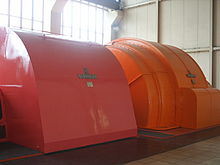
A frequency converter , also known as a frequency converter , is a rotating electrical machine that converts electrical energy at a mains frequency into a voltage with a different frequency . Frequency converters were required to supply consumers or networks with the necessary frequency if this was not made available by the existing network. As a result of the further development of semiconductor components, nowadays electronic frequency converters are mostly used instead of mechanical frequency converters (also referred to as static frequency converters ), except in some railway power converter plants .
Basics
Frequency converters generate a three-phase current with a lower or higher frequency, depending on the design, between 6 Hz and 800 Hz. Three-phase asynchronous motors are usually used as drive machines or, in certain applications, three-phase synchronous motors . Due to the rigid coupling , the mechanical speed of the frequency converter ( generator ) is just as high as that of the electric motor .
Advantages and disadvantages compared to frequency converters
If frequency converters are used for frequency conversion, network perturbations can be excluded. In addition, there are specific properties of rotating machines compared to static converters (high short-circuit currents, inertia of the rotating masses, etc.). A voltage with a low harmonic component is also made available to the consumer . The overall efficiency is made up of the product of the two efficiencies of the motor and generator and is usually above 0.5.
Designs
Frequency converters can be single machines as well as machine sets.
- Smaller frequency converters are designed as single-shaft converters . The rotors of both machines sit on a common shaft and the windings and laminated cores of both stators sit in a common housing .
- For larger machines used Zweimaschinensatzumformer . Here two separate machines are coupled together.
Types
There are the following types of frequency converters:
- Asynchronous frequency converters (three-phase asynchronous motor as drive)
- Synchronous frequency converters (three-phase synchronous motor as drive)
- Frequency converter with commutator .
Asynchronous frequency converters
Asynchronous frequency converters generate higher frequencies, which means that three-phase motors can be operated at higher speeds.
construction
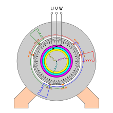
Asynchronous frequency converters consist of a driving three-phase asynchronous motor and a mechanically coupled slip-ring motor . The stator windings of both machines of the asynchronous frequency converter are connected to the mains via a switch . The output network for the consumers is connected to the slip rings of the slip ring rotor. Depending on the rotor design, the rotor voltage is between 42 volts and 500 volts. Slip-ring machines, where the output voltage is less than 125 volts, have a very high output current. A different circuit variant is used for these machines. The output network (secondary network) is connected to the stator winding and the input network (primary network) is connected to the rotor of the slip ring rotor. The usual circuit variant is as mentioned first.
Frequency conversion
If an alternating voltage is applied to the stator of a slip ring motor, a three-phase voltage can be picked up at the three rotor terminals. This is the rotor standstill voltage specified on the rating plate. This is the so-called transformer effect with slip s = 100% and the frequency . If the slip ring motor is driven, the frequency of this three-phase voltage is variable. When turning in the direction of the rotating field , the cutting speed is reduced. As a result, the rotor frequency and the rotor voltage decrease proportionally with the slip.
The frequency and the voltage can therefore only be increased by increasing the cutting speed. The cutting speed, in turn, can be increased in two ways:
- the rotor is driven much faster in the rotating field direction. This is known as negative slip
- The rotor is driven against the rotating field. This is known as inverse slip. ( s> 100% ) or inverse direction. This type of drive is predominant in practice.
The frequency of the rotor voltage and the rotor current is dependent on the slip speed at a given speed and changes proportionally according to the following equation:
Source:
function
In the usual circuit variant, the three-phase current from the primary network generates a rotating magnetic field in the stator winding . The rotating field induces an alternating voltage in the rotor windings, which can be tapped at the slip rings . When the rotor is at a standstill, the frequency of the rotor voltage is just as high as the network frequency of the primary network. This is due to the fact that the rotational speed of the rotating field is the same for both windings. If the rotor is driven with the drive motor in the direction of the rotating field, the output frequency becomes lower, which can be seen from the formula:
A frequency increase can only be achieved here by driving the frequency converter above the nominal speed.
If the rotor is driven against the stator rotating field, the rotor winding intersects the field lines more often than at standstill. The consequence of this is that the output frequency is greater than the input frequency. The frequency is determined with drive against the rotating field according to the following formula:
The speed of the driving machine, on the one hand, and the number of pole pairs of the slip-ring machine, on the other, have a further influence on the output frequency . If the number of pole pairs of the generator is greater than that of the motor, the output frequency is higher than the mains frequency. Conversely, the output frequency is lower if the number of pole pairs of the motor is higher than that of the generator. If the number of pole pairs of both the frequency converter and the motor and the frequency is known, the output frequency can be roughly determined using the following formulas , neglecting the slip :
- Idle frequency with the same rotating field direction
- Idle frequency with unequal rotating field direction
Source:
For a frequency converter with a 2-pole motor and a 4-pole generator, this means when operating on a 50 Hz network:
- with the same rotating field direction, the output frequency is 50 Hz.
- if the rotating field direction is not the same, the output frequency is 150 Hz.
With an appropriate speed of the drive motor and with a suitable number of poles of the slip ring rotor, frequencies up to about 500 Hz can be achieved. Modern frequency converters with output frequencies of up to 800 Hz are manufactured for special areas. If the rotating field is made switchable with a reversing switch, the same converter can be used to supply two frequencies. This frequency switching option is often used at frequencies above 200 Hz. However, the voltage also changes with the frequency; if the frequency is doubled, the voltage is also twice as high. With a known output voltage and known output frequencies and the output voltage can use the following formula to determine:
Source:
Operating behavior
If the converter is loaded, the drive motor is also loaded. As a result, the drive motor rotates more slowly by the amount of slip . This change in the speed of the drive motor also changes the secondary frequency of the frequency converter. Since the slip in three-phase motors is low, the change in the secondary frequency is also small. Since the load on the frequency converter causes the speed to decrease somewhat, stray field lines form in it. In addition, the internal resistance of the output winding causes voltage drops. When loaded, the voltage drops by around 10% compared to the open circuit voltage. When the load is removed, the tension rises again. When using pole-changing drive motors, the frequency converter can supply several frequencies, but the voltage is then different for each frequency.
Areas of application
Asynchronous frequency converters are used particularly as high-speed frequency converters. These high-speed alternating currents (100 Hz - 500 Hz) are required to drive high-speed induction motors. Frequency converters are used in particular where high speeds of up to 18,000 are required. For laboratory use, the frequency converter is equipped with a variable speed drive. This technology can be used to generate a three-phase voltage with an adjustable frequency. Typical application examples are in the area of woodworking machines, drilling machines with induction motors, grinding machines with induction motors, ground power supplies for airports, supply of ships, test fields, radar and in laboratory operations.
Since asynchronous frequency converters are very robust, they were able to hold their own against frequency converters.
Synchronous frequency converters
Synchronous frequency converters are constructed like asynchronous frequency converters with the only difference that the driving machine is a three-phase synchronous motor, which is mainly a reluctance motor in smaller machine sets . This achieves a load-independent speed and better voltage constancy.
Frequency converter with commutator
Frequency converters with commutators are mainly used to generate very low-frequency AC voltages and thus to drive slowly running machines.
Two machine types have maintained a niche position here:
- Slip frequency converter
- Integrated dynamic frequency converter.
Slip frequency converter
construction
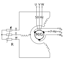
The slip frequency converter is constructed similarly to the three-phase DC single armature converter , but it does not have an exciter winding. The starting winding is connected to a variable resistor and not short-circuited. As a result of this measure, the converter cannot become synchronized even after it has started up. A large amount of slippage is caused by mechanical stress from large ventilation blades, which can be controlled by the variable resistor.
function
The three-phase current generates a rotating field in the stator winding, which rotates at a speed that corresponds to the slip frequency. Since each winding between two brushes acts like a coil, a current can be drawn from the collector via the brushes that also corresponds to the slip frequency. The commutator acts like a frequency converter here.
Operating behavior
Slip frequency converters thus deliver frequencies that are significantly lower than the mains frequency: 6 Hz - 16 Hz depending on the slip. On the output side, the voltage is fairly independent of the frequency.
Areas of application
To control the speed of three-phase squirrel cage motors, slip frequency converters are still used today. However, their importance has decreased significantly due to the use of modern power electronics in frequency converters. Typical areas of application are crane systems.
Integrated dynamic frequency converter
The integrated dynamic frequency converter, also called Schrage- Richter motor or Scherbius machine after its developer, also belongs to the group of alternating current commutator machines. Unlike other frequency converters, this machine does not feed any power to the outside, but only uses the frequency conversion to change the speed inside the machine.
construction
The stator windings are connected to the commutator and thus to the rotor winding via carbon brushes . The brushes can be moved in both directions. The rotor has two windings, a control winding and an excitation winding. The control winding is connected to the commutator. The excitation winding is connected to the network.
function
If the machine with the field winding is connected to the mains, a current flows in the field winding. This current flow in the field winding induces currents in the control windings. The rotating field created by the rotor wants to make the stator rotate. But this is not possible. Therefore it begins to rotate itself. Depending on the position of the brushes, it is possible to change the speed in either subsynchronous or oversynchronous ranges.
Areas of application
The machines were manufactured as rotor and stator-fed versions with outputs of 150 kW - 1500 kW; the runner-fed version prevailed. Due to its complex design and maintenance, this machine is only used today for a few actuators and regulating drives. Typical areas of application are heavy, textile and sugar industries.
Statutory provisions and other regulations
- EN 60 034 Part 1 General provisions for rotating electrical machines
- EN 60 034 part 8 Terminal designations and direction of rotation for electrical machines
- DIN IEC 34 Part 7 Types of rotating electrical machines
- EN 60034-5 Degrees of protection of rotating electrical machines
- EN 60034-6 Types of cooling for rotating electrical machines
Individual evidence
- ↑ a b c d e f g A. Senner: Electrical engineering. 4th edition. Verlag Europa-Lehrmittel, 1965.
- ↑ a b c d e Rolf Fischer: Electrical machines. 12th edition, Carl Hanser Verlag, Munich and Vienna 2004, ISBN 3-446-22693-1 .
- ↑ a b c d Ernst Hörnemann, Heinrich Hübscher: Electrical engineering specialist training in industrial electronics. 1st edition. Westermann Schulbuchverlag GmbH, Braunschweig, 1998, ISBN 3-14-221730-4 .
- ↑ a b c Günter Boy, Horst Flachmann, Otto Mai: The master's examination in electrical machines and control technology. 4th edition, Vogel Buchverlag, Würzburg, 1983, ISBN 3-8023-0725-9
- ^ A b Günter Springer: Electrical engineering. 18th edition, Verlag Europa-Lehrmittel, Wuppertal, 1989, ISBN 3-8085-3018-9 .
- ↑ Kemmerich Elektromotoren Frequency Converter Online (accessed on July 13, 2012; PDF file; 1.6 MB).
- ↑ a b c Ali Farschtschi: electric machines in theory and practice. 1st edition, VDE-Verlag GmbH, Berlin and Offenbach 2001, ISBN 3-8007-2563-0
- ^ Paul Rauhut: About the circle diagram of the Schrage motor. Doctoral thesis, Eidgenössische Technische Hochschule Zürich Online (accessed on July 16, 2012).
See also
Web links
- Max Leumann: Cascade connections of three-phase asynchronous machines with commutator machines for phase compensation. Buchdruckerei Karl Werner, Basel 1933 Online (accessed July 16, 2012)


