
Electric generator
An electric generator (for Latin generare , bring out ',' produce ') is an electric machine , the kinetic energy in electric energy transforms. The generator is the counterpart to the electric motor , which converts electrical energy into kinetic energy. It is based on the principle of electromagnetic induction discovered by Michael Faraday in 1831 .

Mode of action


The principle of converting mechanical power into electrical power is the same for all electrical generators that work by means of electromagnetic induction . The mechanical power is supplied to the generator in the form of the rotation of a mechanical shaft . The conversion is based on the Lorentz force , which acts on moving electrical charges in a magnetic field. If a conductor moves across (perpendicular) to the magnetic field , the Lorentz force acts on the charges in the conductor in the direction of this conductor and sets them in motion. This charge shift causes a potential difference and generates an electrical voltage between the ends of the conductor. In the adjacent animation, only the displacement of the conductor (or the two relevant coil sections) perpendicular to the magnetic field is relevant. This is illustrated by the red area. The greater the change in area per time change (distance traveled by the conductor), the higher the voltage. To increase the voltage, several conductors connected in series in the form of a coil are used.
This mode of operation must be distinguished from that of electrostatic generators , in which the separation of electrical charges is carried out by the electric and not by the magnetic field.
Inside the generator, the rotor (also called rotor ) is rotated relative to the stationary stator housing (also called stator ). The constant magnetic field generated by the rotor with a permanent magnet or an electromagnet (called field coil or excitation winding ) induces electrical voltage in the conductors or conductor windings of the stator by the Lorentz force.
With direct current generators , the current is induced in the rotor ( armature ), the field coil or permanent magnet is outside. The generated current is rectified with a commutator .
The electrical power generated is equal to the mechanical power minus the losses that occur. The power equation of an electrical generator follows from this:

is the generated electrical power, is the supplied mechanical power, is the power loss due to mechanical friction, copper losses and iron losses .


The voltage drawn can be controlled via the strength of the excitation field if this is generated by an electromagnet (electrical excitation, external excitation). This control method is not only used in power plants, but also e.g. B. also used in alternators of motor vehicles (alternator regulator).
construction

Rotary generator

In order to generate a sinusoidal voltage in an alternating current or three-phase synchronous generator, the rotor must generate a magnetic field that is as homogeneous as possible . In addition to the field coil, it also has pole shoes with a mushroom-shaped cross-section, which distribute the magnetic field. The number of poles (at least two, other even numbers possible) determines the frequency of the voltage output at a given speed. The field winding must be attached very well so that it can withstand the high centrifugal forces. One operating condition to be avoided is load shedding , which would destroy the generator without the intervention of a controller because the increasing speed of the driving steam or gas turbine leads to excessive centrifugal forces in the armature windings. The rotor with permanent magnet -erregten generators, squirrel cage - or asynchronous generators requires no power supply, for synchronous generators, the power is supplied via slip rings . With auxiliary generators on the same shaft, slip rings can be dispensed with with synchronous generators.
The generator windings are distributed internally in several grooves of the hollow-cylinder-shaped stator laminated core. The grooves filled with the windings narrow towards the inside again and also form pole shoes. The outer jacket of the laminated core does not contain any windings, it serves as a yoke or magnetic return path to concentrate the alternating magnetic field in the windings.
Direct current generators require a commutator ( commutator ) to take and rectify the voltage generated in the rotor. Since the entire electrical power generated has to be transferred via the commutator, they are no longer in use today. To obtain a direct voltage, alternating current generators with downstream rectifiers are usually used, for example in the case of a generator in a motor vehicle (commonly known as an alternator ).
Asynchronous generators are constructed just like asynchronous motors . They have neither a field coil nor slip rings, but a squirrel-cage rotor . The magnetic field circulating with it is generated by the current in the generator windings. Asynchronous generators can therefore only deliver electricity if they are connected to an alternating voltage or are already generating electricity. In isolated operation, they are loaded with capacitors and often have a small permanent magnet in the rotor at the start. However, the residual magnetization is often sufficient.
Almost all of the more modern, low-power generators are three-phase asynchronous machines , while large generators (from approx. 0.1 MW), but also the generator in motor vehicles and bicycles, are synchronous machines. Only synchronous machines are able to provide the reactive power required in power plants in addition to the active power.
Linear generator

A linear generator (also called induction or shaking generator ) in its simplest form can be implemented with the Stelzer motor . In this case, there is a coil on both sides of the free-swinging piston, into which the end of the piston, on which a magnet is located, is immersed. The frequency of the alternating voltage generated depends on the frequency of the freely oscillating piston and fluctuates depending on the load.
A special application example for this technology are the shaking flashlights . The shaking movement causes a strong neodymium magnet to move through a coil. The voltage generated is sufficient to charge a double-layer capacitor (1 to 2 farads, 3 to 4 volts), which can then supply one or more LED lamps with power for a longer period of time. Another application example for linear generators are accumulators equipped with them (e.g. in AA or AAA format ), which can be used universally for similarly economical devices.
Power plant generators
Power plants mostly use three-phase synchronous machines , which are mostly designed as internal pole machines. They consist of:
- Stator , which is a large induction coil with an iron core . The stator is not a solid iron body, but is made up of many individual sheet metal lamellas that are isolated from one another to avoid eddy currents . For large generators, these blades are made of non-grain dynamo sheet produced more rarely from grain-oriented dynamo sheet.
- Rotor: the rotating part of the generator consists of the bearings and a forged, i.e. massive full drum rotor (roller rotor). No eddy currents occur in the rotor when the load is symmetrical, which is why the lamination can be omitted. Mechanical power is supplied to the rotor via the shaft.
The large generators used today for power plants are almost without exception full-pole machines for a (country-specific) network frequency of 50 or 60 Hz.
High-speed synchronous generators , as used in combination with steam turbines in power plants, are called turbo generators or full-pole machines. Your excitation field typically has two or four poles . In modern systems, the excitation winding is fed according to the principle of brushless or static excitation . In hydroelectric power plants , salient pole machines with significantly more than four poles are typically used due to the low speed of the turbines .
The advantage of synchronous generators compared to asynchronous generators is that, depending on the control, they can supply or absorb both active power and inductive or capacitive reactive power to the supply network. Depending on the level of their magnetic excitation , synchronous generators emit pure active power or additionally supply reactive power into the network , which is required to compensate for inductive and capacitive loads . They can thus serve as active phase shifters in electrical power supply networks .
Asynchronous generators are of no importance as generators in large power plants. Some of them are used in diesel generators, small hydropower plants and wind turbines (90% worldwide). In principle, they represent an inductive reactive load.
The strand coils of large generators heat up considerably during operation and must therefore be cooled. The coils in the stator are cooled with water, while those in the rotor are cooled with hydrogen , which circulates through the generator housing under a pressure of up to 10 bar and gives off its heat in a downstream heat exchanger . With hydrogen ( specific heat capacity = 14.3 J / (gK)), significantly better cooling is achieved with less friction than with air (only 1 J / (gK)). Generators with an output of less than 300 MVA are mostly air-cooled. The air circulates in the housing and through the coils in the stator. The fans are attached directly to the rotor. The air is cooled with water coolers, which are located directly in the lower part of the generator housing.
The generators for generating traction current are a specialty . Because of the single-phase voltage with approximately 16.7 Hz, these generators are designed as AC synchronous machines and rotate at a speed of 1000 revolutions per minute (1/3 the speed of 50 Hz Generators). Their frequency was formerly at 50 Hz / 3 = 16 2 / 3 Hz and was later due to technical reasons changed . The magnetic flux within these generators is three times greater than the flux in 50 Hz machines with the same power. Traction current generators therefore require correspondingly larger cross-sections made of iron. For this reason they are significantly larger than comparable 50 Hz generators. In addition, there is a rotating and pulsating torque on the drive at twice the mains frequency . This pulsation also affects the foundations of the machine; the generator is therefore placed on springs. For the same reason, an elastic coupling is connected between the drive and the generator . Traction current generators are mostly driven by electric motors from the power grid (the combination is called a converter ), the device is called a converter plant . Today traction current is partly generated electronically from the mains voltage in converter plants.
The world's largest three-phase synchronous generator for the Finnish Olkiluoto nuclear power plant was manufactured at the Siemens plant in Mülheim . It has a rated apparent power of 1992 MVA.
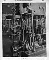
Speed regulator on a steam engine driven generator (around 1900)

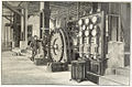
Steam engine-driven , 56-pole generator with six-pole exciter (built in 1910; 650 kW)
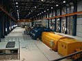
Generator in the Schwarze Pump power plant (1995; 1000 MVA)

Turbo generator with steam turbine in a nuclear power plant


history
First generation of electricity by induction
Hippolyte Pixii built the first known alternator at the suggestion of Ampère , the model (see gallery) was made in 1832 from two coils under which a horseshoe magnet rotates. The current is rectified in the machine by a commutator. In the same year, Michael Faraday built a unipolar machine that generates a direct current through unipolar induction when the cylindrical permanent magnet rotates on the axis of rotation . Also in 1832, Salvatore Dal Negro constructed a vibrating device for generating; other non-rotating power generators were built by Carl Friedrich Gauß and others.
First large-scale use of alternators
The AC generator from the Alliance company (see gallery) based on a suggestion by Floris Nollet (Brussels) in 1849 was the first generator to be used significantly in industry. The intended purpose of the machines was to electrochemically break down water in order to obtain luminous gas for lighting. In fact, most of the machines were used without a commutator in English and French lighthouses to operate arc lamps . The last ones were not taken out of service until the turn of the 20th century.
First generators without permanent magnets
The preferred inventor of the generator without permanent magnets is Werner von Siemens , who discovered the dynamo-electric principle in 1866 and equipped the first dynamo machine with it. Even before Siemens, however, Ányos Jedlik in 1851 and Søren Hjorth in 1854 had supplied the field magnets with the electricity generated by the machine itself and described this. At the same time as Siemens, Samuel Alfred Varley and Charles Wheatstone discovered and published this principle, whereby the Wheatstone variant later turned out to be the more technically important one.
First polyphase alternators
As part of the Frankfurt International Electrotechnical Exhibition in 1891, AC machines were demonstrated that were specially built to generate multi-phase alternating current. Friedrich August Haselwander built the first of these generators in 1887. This was already delivering three-phase alternating current . The American Charles Bradley acquired a patent for a two-phase alternator in early 1897 . An AC machine from Schuckert and a generator from Brown, Boveri & Cie. (see gallery). The first two-phase power plant of the Austro-Hungarian monarchy was built by Franz Pichler and went into operation in the Raabklamm near Weiz in Styria in 1892 . After a few years, this generator was rewound for three-phase current and was in operation until 1971.
First large-scale power plants
In the period that followed, numerous power plants were built, some of which got their energy from hydropower and some from steam . In 1895, the world's first large power plant was connected to the grid in / Am Niagara , and as early as 1898 the Rheinfelden power transmission plant in Europe followed as a river power plant. A steam power station brought the Budapest electricity company on line as early as 1895.

First known magneto-electric alternating current machine, built in 1832 by Hippolyte Pixii

AC generator from the Alliance company based on a suggestion by Professor Nollet (Brussels) from 1849

Drawing of an alternator from 1891 after Charles Eugene Lancelot Brown ( Brown, Boveri & Cie. )
Contemporary wood engraving of the generator room in the first three-phase power plant in Lauffen am Neckar , which supplied an artificial waterfall and a thousand light bulbs for the electrotechnical exhibition in Frankfurt on September 12, 1891. This C. E. Brown development was still produced by the Oerlikon machine factory .
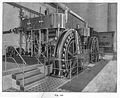
Steam engine- powered two-phase power generator with ring armature for the Budapest power station in 1895


See also
- Outer pole generator
- Internal pole generator
- Main circuit generator (series generator)
- Shunt generator
- Double-circuit generator (generator compound)
- Bicycle dynamo
- Van de Graaff generator
- Cascade machine
- Unipolar machine
- Electric motor
- Magnetohydrodynamic generator
literature
- Ansgar Christ: Motors, Generators, Transformers: Workbook . Stam, Cologne 1999, ISBN 3-8237-3414-8
- Günter Franz: Rotating electrical machines: generators, motors, converters . 8th edition, Verlag Technik, Berlin 1990, ISBN 3-341-00143-3
- Klaus Heuck, Klaus-Dieter Dettmann, Detlef Schulz: Electrical energy supply: generation, transmission and distribution of electrical energy for study and practice . 9th edition, Springer Vieweg, Wiesbaden 2013, ISBN 978-3-8348-1699-3
- Reinhard Mayer: Generators and starters . Robert Bosch, Stuttgart 2002, ISBN 3-7782-2028-4
- Friedrich Niethammer : Single and multi-phase alternating current generator . Hirzel, Leipzig 1906, 460 pages (748 images)
Web links
- Animated model of the generator principle , www.walter-fendt.de
- Brief overview at the end of the document (history - species - induction law), www.hellfirez.de
Individual evidence
- ↑ Shaking battery: Charging AA and AAA batteries by shaking - Article at Golem.de , July 19, 2010
- ↑ http://antriebstechnik.fh-stralsund.de/1024x768/Dokumentenframe/Kompendium/Antriebstechnik/S_Info_Drehstromgeneratoren.htm
- ↑ http://www.derwesten.de/staedte/muelheim/Abschied-von-900-Tonnen-id1284260.html
- ^ Deutsches Museum: Werner Siemens' dynamo machine, history of discovery